Anritsu_MG3692C.PDF - 第4页
4 Spectral Purity All specifications apply at the lesser of +10 dBm output or maximum specified leveled output power , unless otherwise noted. Spurious Signals Frequency Switching Time Definitions Free Running Mode: (Ste…

3
General
Stored Setups: Stores front panel settings and nine additional front-panel setups in
a non-volatile RAM. A system menu allows saving and recalling of instrument setups.
Whenever the instrument is turned on, control settings come on at the same functions
and values existing when the instrument was turned off.
Memory Sequencing Input: Accepts a TTL low-level signal to sequence through ten
stored setups. AUX I/O connector, rear panel.
Self-Test: Instrument self-test is performed when Self-Test soft-key is selected. If an
error is detected, an error message is displayed in a window on the LCD identifying the
probable cause and remedy.
Secure Mode: Disables all frequency and power level state displays. Stored setups
saved in secure mode remain secured when recalled. Mode selectable from a system
menu and via GPIB.
Parameter Entry: Instrument-controlled parameters can be entered in three ways:
keypad, rotary data knob, or the ∧ and ∨ touch pads of the cursor-control key. The
keypad is used to enter new parameter values; the rotary data knob and the cursor-
control key are used to edit existing parameter values. The < and > touch pads of the
cursor-control key move the cursor left and right one digit under the open parameter.
The rotary data knob or the < and > touch pads will increment or decrement the digit
position over the cursor. Controlled parameters are frequency, power level, sweep
time, dwell time, and number of steps. Keypad entries are terminated by pressing the
appropriate soft key. Edits are terminated by exiting the edit menu.
Reset: Returns all instrument parameters to predefined default states or values.
Any pending GPIB I/O is aborted. Selectable from the system menu.
Master/Slave Operation: Allows two output signals to be swept with a user-selected
frequency offset. One instrument controls the other via AUX I/O and SERIAL I/O
connections. Requires a Master/Slave Interface Cable Set (Part No. ND36329).
User Level Flatness Correction: Allows user to calibrate out path loss due to external
switching and cables via entered power table from a GPIB power meter or calculated
data. When user level correction is activated, entered power levels are delivered at the
point where calibration was performed. Supported power meters are Anritsu ML2437A,
ML2438A, ML2480A/B, ML2490A, and ML4803A and HP 437B, 438A, and 70100A.
Five user tables are available with up to 801 points/table.
Warm Up Time:
From Standby: 30 minutes.
From Cold Start (0 deg C): 120 hours to achieve specified frequency stability with aging.
Instruments disconnected from AC line power for more than 72 hours require
30 days to return to specified frequency stability with aging.
Power: 85 Vac - 264 Vac, 48 Hz - 440 Hz, 250 VA maximum
Standby: With ac line power connected, unit is placed in standby when front panel power
switch is released from the OPERATE position.
Weight: 18 kg maximum
Dimensions: 133 H x 429 W x 450 D mm
Warranty: 3 years from ship date
Remote Operation
All instrument functions, settings, and operating modes (except for power on/standby)
are controllable using commands sent from an external computer via the GPIB
(IEEE-488 interface bus).
GPIB Commands: Native, SCPI
GPIB Address: Selectable from a system menu
IEEE -488 Interface Function Subset:
Source Handshake: SH1
Acceptor Handshake: AH1
Talker: T6
Listener: L4
Service Request: SR1
Remote/Local: RL1
Parallel Poll: PP1
Device Clear: DC1
Device Trigger: DT1
Controller Capability: C0, C1, C2, C3, C28
Tri-State Driver: E2
GPIB Status Annunciators: When the instrument is operating in Remote, the GPIB
status annunciators (listed below) will appear in a window on the front panel LCD.
Remote: Operating on the GPIB (all instrument front panel keys except for the SYSTEM
key and the RETURN TO LOCAL soft-key will be ignored).
LLO (Local Lockout): Disables the RETURN TO LOCAL soft-key. Instrument can
be placed in local mode only via GPIB or by cycling line power.
Emulations: The instrument responds to the published GPIB commands and responses
of the Anritsu Models 6600, 6700,and 6XX00-series signal sources. When emulating
another signal source, the instrument will be limited to the capabilities, mnemonics, and
parameter resolutions of the emulated instrument.
Environmental (MIL-PRF-28800F, class 3)
Storage Temperature Range: –40 °C to +75 °C
Operating Temperature Range: 0 °C to +50 °C
Relative Humidity: 5% to 95% at 40 °C
Altitude: 4,600 meters, 43.9 cm Hg
EMI: Meets the emission and immunity requirements of
EN61326: 1998
EN55011: 1991/CISPR-11:1990 Group 1 Class A
EN61000-4-2: 1995 – 4 kV CD, 8 kV AD
EN61000-4-3: 1997 – 3 V/m
EN61000-4-4: 1995 – 0.5 kV SL, 1 kV PL
EN61000-4-5: 1995 – 1 kV – 2 kV L-E
EN61000-4-6: 1996
EN61000-4-11: 1994
Vibration: Random, 5 Hz - 500 Hz, 0.015-0.0039g
2
/Hz PSD
Sinusoidal, 5 Hz - 55 Hz, 0.33 mm displacement
Safety Directive: EN 61010-1: 1993 + A1: 92 + A2: 95
4
Spectral Purity
All specifications apply at the lesser of +10 dBm output or maximum specified leveled
output power, unless otherwise noted.
Spurious Signals
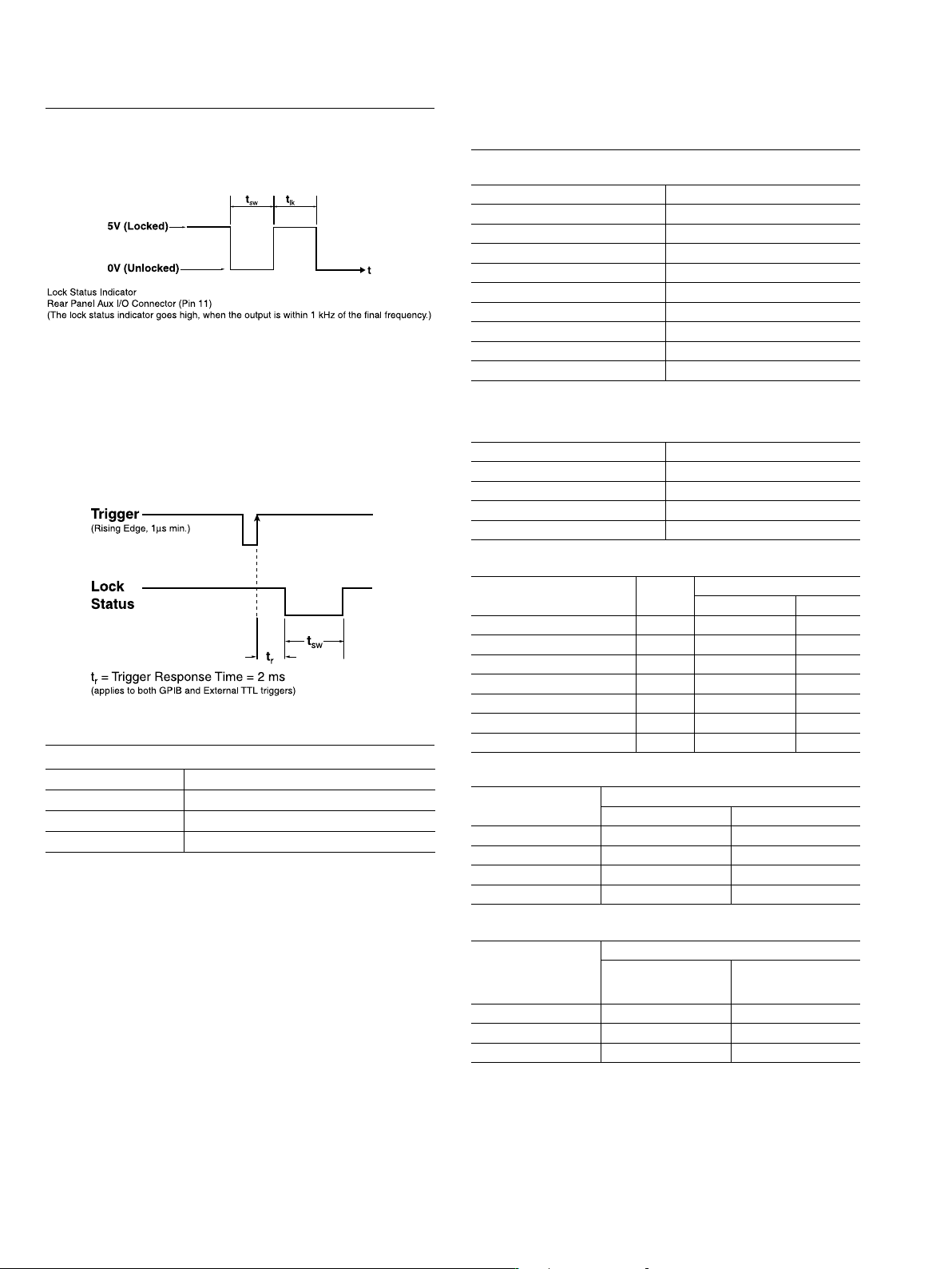
Frequency Switching Time
Definitions
Free Running Mode:
(Step or List Sweep)
t
sw
= Switching Time, Unlocked
t
lk
= Locked Time = 1ms + t
dw
t
dw
= Dwell Time, after locking. Selectable, 1 ms minimum
t
lk
(min) = 2 ms
Single Frequency Trigger Mode:
(List, non-sequential, and CFx modes)
Switching Time (t
sw
)
Power Line and Fan Rotation Spurious Emissions (dBc):
Residual FM* (CW and Step Sweep modes, 50 Hz - 15 kHz BW) (typical):
Non-harmonics:
AM Noise Floor:
Typically < –145 dBm/Hz at 0 dBm output and offsets > 5 MHz from carrier.
Residual FM* (Analog Sweep and Unlocked FM modes, 50 Hz - 15 kHz BW) (typical):
* –30 dBc typical with high power Option 15
=
20 GHz to 21 GHz and 39 GHz to 40 GHz, –20 dBc typical (Option 15 only)
Harmonic and Harmonically-related:
t
sw
*
(ms)
Condition
5 ms + 1 ms/GHz step not starting at, or crossing dwell frequencies
7 ms + 1 ms/GHz (typical) step not starting at, or crossing band switching frequencies
8 ms + 1 ms/GHz (typical) step starting at, or crossing band switching frequencies
Frequency Range Standard
0.1 Hz to 10 MHz (Option 22) < –30 dBc
10 MHz to ≤ 100 MHz (Option 4)
< –40 dBc
> 100 MHz to ≤ 2.2 GHz (Option 4) < –50 dBc
10 MHz to ≤ 50 MHz (Option 5) < –30 dBc
> 50 MHz to < 2 GHz (Option 5) < –40 dBc
2 GHz (> 2.2 GHz w/Option 4) to ≤ 20 GHz < –60 dBc*
> 20 GHz to ≤ 40 GHz < –40 dBc*
=
> 40 GHz to ≤ 50 GHz (MG3695B) < –40 dBc*
> 40 GHz to ≤ 67 GHz (MG3696B) < –25 dBc
Frequency Range Standard
0.1 Hz to 10 MHz (Option 22) < –30 dBc
10 MHz to ≤ 2.2 GHz (Option 4) < –60 dBc
10 MHz to ≤ 2 GHz (Option 5) < –40 dBc
> 2 GHz (2.2 GHz w/Option 4) to ≤ 67 GHz < –60 dBc
Frequency 300 Hz
Offset from Carrier
300 Hz to 1 kHz > 1 kHz
10 MHz to ≤ 500 MHz (Option 4) < –68 < –72 < –72
> 500 MHz to ≤ 1050 MHz (Option 4) < –62 < –72 < –72
> 1050 MHz to ≤ 2200 MHz (Option 4) < –56 < –66 < –66
0.01 GHz to ≤ 8.4 GHz < –50 < –60 < –60
> 8.4 GHz to ≤ 20 GHz < –46 < –56 < –60
> 20 GHz to ≤ 40 GHz < –40 < –50 < –54
> 40 GHz to ≤ 67 GHz < –34 < –44 < –48
Frequency Range
Resid ual FM (Hz RMS)
Option 3/3X Standard
≤ 8.4 GHz < 40 < 120
> 8.4 GHz to 20 GHz < 40 < 220
> 20 GHz to ≤ 40 GHz < 80 < 440
> 40 GHz to ≤ 67 GHz < 160 < 880
Frequency Range
Resid ual FM (kHz RMS)
Unlocked Narrow
FM mode
Unlocked Wide
FM mode or
Analog Sweep (typ.)
0.01 GHz to ≤ 20 GHz < 10 < 25
> 20 GHz to ≤ 40 GHz < 20 < 50
> 40 GHz to ≤ 67 GHz < 40 < 100
Band Switching Dwell Frequencies: 2 (2.2 w/Opt. 4), 10, 20, 40 GHz
Filter Switching Dwell Frequencies: 3.3, 5.5, 8.4, 13.25, 25, 32 GHz
< 2.2 GHz w/Opt. 4: 12.5, 15.625, 22.5, 31.25, 43.75, 62.5, 87.5,
125, 175, 250, 350, 500, 700, 1050, 1500 MHz
*Not applicable with FM mode active
*Residual FM is not applicable with FM locked mode
55
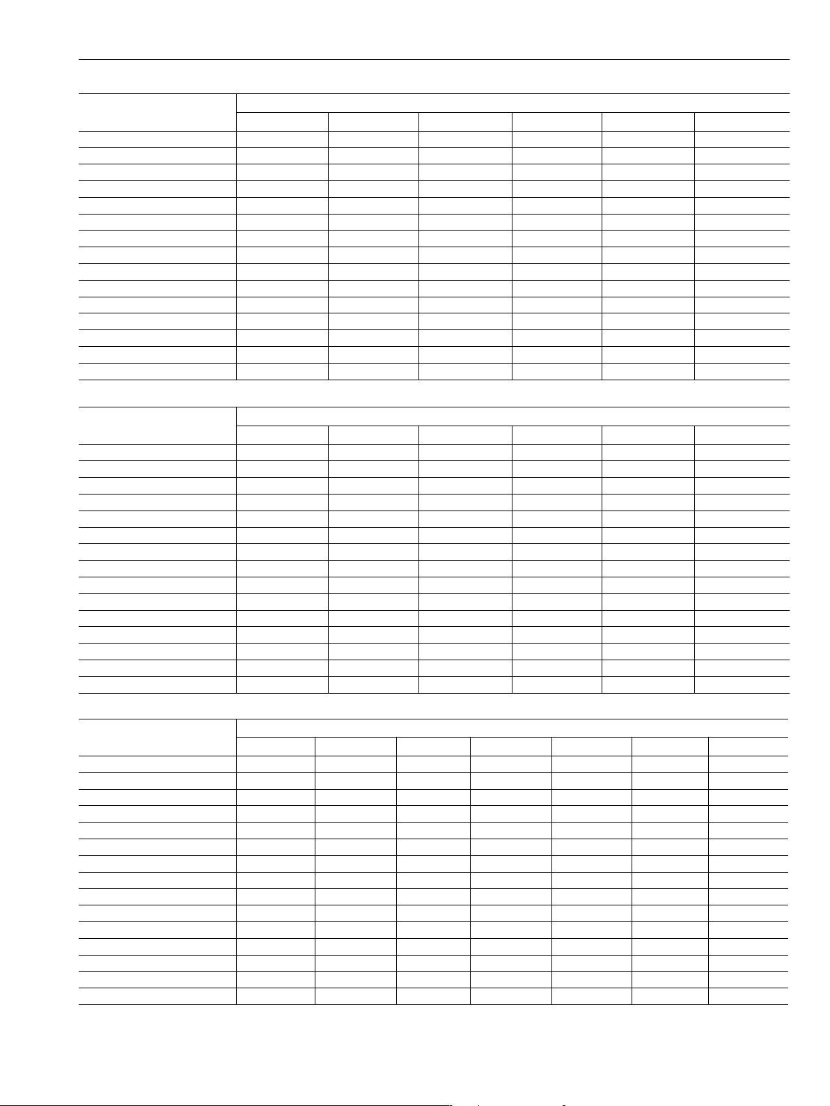
Single-Sideband Phase Noise (dBc/Hz): (Typical)
Frequency Range
10 Hz 100 Hz 1 kHz 10 kHz 100 kHz 1 MHz
0.1 Hz to <10 MHz (Option 22) –80 (–100) –90 (–110) –120 (–125) –130 (–139) –130 (–141) –130 (–141)
10 MHz to 15.625 MHz (Option 4) –102 (–113) –128 (–133) –142 (–149) –145 (–152) –145 (–153) –145 (–153)
>15.625 Mhz to 31.25 MHz (Option 4) –97 (–109) –125 (–130) –142 (–147) –144 (–149) –144 (–153) –145 (–155)
>31.25 MHz to 62.5 MHz (Option 4) –92 (–104) –122 (–128) –140 (–146) –142 (–146) –143 (–150) –145 (–155)
>62.5 MHz to 125 MHz (Option 4) –87 (–98) –114 (–118) –133 (–139) –130 (–140) –130 (–143) –145 (–155)
>125 MHz to 250 MHz (Option 4) –82 (–93) –108 (–113) –126 (–134) –124 (–134) –124 (–138) –145 (–153)
>250 MHz to 500 MHz (Option 4) –75 (–87) –102 (–109) –120 (–128) –118 (–127) –118 (–130) –143 (–149)
>500 MHz to 1050 MHz (Option 4) –70 (–80) –94 (–100) –115 (–123) –115 (–122) –116 (–126) –138 (–144)
>1050 MHz to 2200 MHz (Option 4) –65 (–74) –86 (–96) –113 (–117) –111 (–116) –114 (–120) –133 (–139)
10 MHz to <2000 MHz (Option 5) –62 (–72) –85 (–95) –100 (–104) –102 (–106) –102 (–106) –111 (–114)
2 GHz to 6 GHz –54 (–64) –81 (–88) –102 (–109) –103 (–110) –106 (–114) –128 (–133)
>6 GHz to 10 GHz –52 (–62) –75 (–85) –98 (–106) –104 (–109) –106 (–113) –126 (–132)
>10 GHz to 20 GHz –45 (–55) –69 (–78) –92 (–101) –98 (–103) –98 (–106) –124 (–131)
>20 GHz to 40 GHz –38 (–48) –62 (–72) –86 (–94) –92 (–100) –92 (–100) –118 (–124)
>40 GHz to 67 GHz –32 (–42) –56 (–66) –80 (–88) –87 (–94) –82 (–91) –112 (–118)
Single-Sideband Phase Noise (dBc/Hz) - Option 3: (Typical)
Frequency Range
10 Hz 100 Hz 1 kHz 10 kHz 100 kHz 1 MHz
0.1 Hz to <10 MHz (Option 22) –80 (–100) –90 (–110) –120 (–125) –130 (–139) –130 (–141) –130 (–141)
10 MHz to 15.625 MHz (Option 4) –102 (–120) –128 (–140) –142 (–150) –145 (–152) –148 (–153) –148 (–152)
>15.625 Mhz to 31.25 MHz (Option 4) –97 (–108) –123 (–128) –141 (–149) –145 (–153) –148 (–153) –148 (–155)
>31.25 MHz to 62.5 MHz (Option 4) –92 (–109) –118 (–131) –139 (–146) –145 (–153) –148 (–153) –148 (–156)
>62.5 MHz to 125 MHz (Option 4) –87 (–98) –113 (–118) –134 (–139) –142 (–147) –143 (–148) –148 (–155)
>125 MHz to 250 MHz (Option 4) –82 (–93) –108 (–113) –129 (–134) –138 (–143) –137 (–142) –148 (–153)
>250 MHz to 500 MHz (Option 4) –77 (–91) –102 (–114) –124 (–130) –132 (–137) –128 (–137) –144 (–153)
>500 MHz to 1050 MHz (Option 4) –72 (–83) –98 (–103) –119 (–123) –126 (–132) –122 (–132) –139 (–150)
>1050 MHz to 2200 MHz (Option 4) –63 (–77) –92 (–101) –113 (–119) –121 (–126) –117 (–125) –134 (–146)
10 MHz to <2000 MHz (Option 5) –62 (–72) –85 (–95) –100 (–104) –102 (–106) –102 (–106) –111 (–114)
2 GHz to 6 GHz –54 (–77) –82 (–93) –106 (–111) –115 (–119) –112 (–119) –138 (–142)
>6 GHz to 10 GHz –52 (–73) –75 (–88) –102 (–109) –113 (–119) –115 (–120) –134 (–140)
>10 GHz to 20 GHz –45 (–66) –69 (–82) –97 (–105) –109 (–115) –109 (–115) –130 (–137)
>20 GHz to 40 GHz –38 (–59) –62 (–75) –90 (–98) –104 (–108) –103 (–109) –122 (–131)
>40 GHz to 67 GHz –32 (–51) –56 (–68) –84 (–91) –97 (–103) –97 (–103) –118 (–125)
Single-Sideband Phase Noise*
* Phase noise is specified and guaranteed only with internal reference. In External Reference mode, the phase noise of the external supplied reference, and the selected external reference bandwidth,
will dictate the instrument phase noise performance. Phase noise is not degraded when adding high power Option 15.
Single-Sideband Phase Noise (dBc/Hz) - Option 3X: (Typical)
Frequency Range
Offset from Carrier
1 Hz 10 Hz 100 Hz 1 kHz 10 kHz 100 kHz 1 MHz
0.1 Hz to <10 MHz (Option 22) –60 (–70) –80 (–100) –90 (–110) –120 (–125) –130 (–139) –130 (–141) –130 (–141)
10 MHz to 15.625 MHz (Option 4) –89 (–103) –111 (–128) –135 (–141) –142 (–150) –145 (–152) –148 (–153) –148 (–152)
>15.625 MHz to 31.25 MHz (Option 4) –85 (–96) –107 (–123) –130 (–137) –141 (–149) –145 (–153) –148 (–153) –148 (–155)
>31.25 MHz to 62.5 MHz (Option 4) –80 (–90) –101 (–118) –124 (–133) –139 (–146) –145 (–153) –148 (–153) –148 (–156)
>62.5 MHz to 125 MHz (Option 4) –74 (–86) –96 (–111) –117 (–127) –134 (–139) –142 (–147) –143 (–148) –148 (–155)
>125 MHz to 250 MHz (Option 4) –68 (–81) –92 (–104) –111 (–121) –129 (–134) –138 (–143) –137 (–142) –148 (–153)
>250 MHz to 500 MHz (Option 4) –62 (–76) –88 (–98) –105 (–115) –124 (–130) –132 (–137) –128 (–137) –144 (–153)
>500 MHz to 1050 MHz (Option 4) –56 (–69) –79 (–92) –99 (–109) –119 (–123) –126 (–132) –122 (–132) –139 (–150)
>1050 MHz to 2200 MHz (Option 4) –49 (–62) –71 (–87) –93 (–103) –113 (–119) –121 (–126) –117 (–125) –134 (–146)
10 MHz to <2000 MHz (Option 5) –38 (–45) –68 (–78) –85 (–95) –100 (–104) –102 (–106) –102 (–106) –111 (–114)
2 GHz to 6 GHz –41 (–52) –65 (–77) –81 (–94) –106 (–111) –115 (–119) –112 (–119) –138 (–142)
>6 GHz to 10 GHz –34 (–46) –62 (–77) –83 (–91) –102 (–109) –113 (–119) –115 (–120) –134 (–140)
>10 GHz to 20 GHz –29 (–42) –59 (–72) –77 (–85) –97 (–105) –109 (–115) –109 (–115) –130 (–137)
>20 GHz to 40 GHz –23 (–36) –53 (–65) –70 (–79) –90 (–98) –104 (–108) –103 (–109) –122 (–131)
>40 GHz to 67 GHz –17 (–30) –47 (–59) –64 (–73) –84 (–91) –97 (–103) –97 (–103) –118 (–125)