Anritsu_MG3692C.PDF - 第14页
14 Ordering Information Models MG3691C 2 GHz - 10 GHz Signal Generator MG3692C 2 GHz - 20 GHz Signal Generator MG3693C 2 GHz - 31.8 GHz Signal Generator MG3694C 2 GHz - 40 GHz Signal Generator MG3695C 2 GHz - 50 GHz Sign…
13
Inputs and Outputs*
*Connectors may be available but not active, if option is not ordered.
** Options (7 & 18), (7 & 20), (8 & 9) are mutually exclusive, as they share the same
rear panel space.
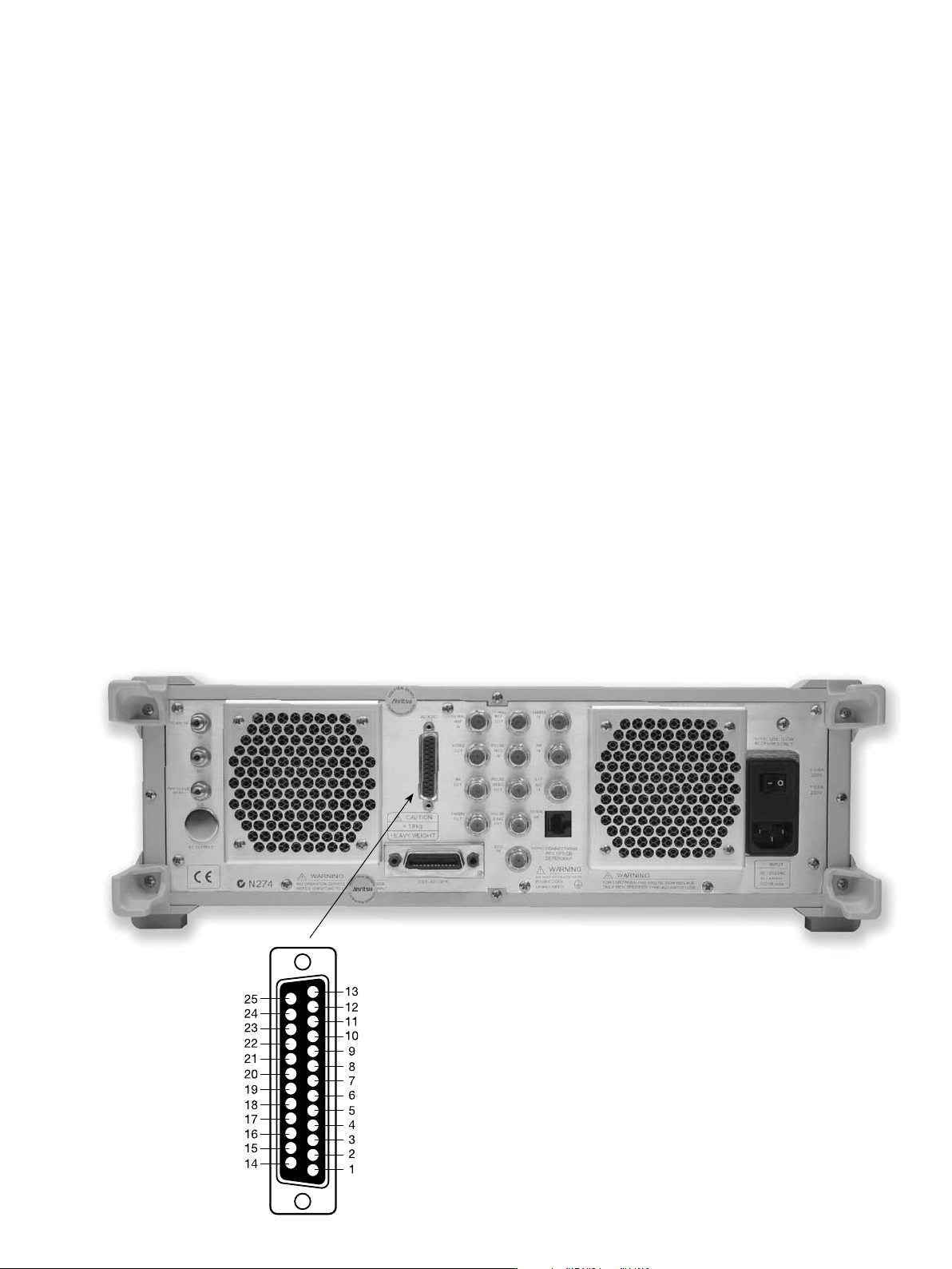
MG3690C Rear Panel
EXT ALC IN Provides for leveling the RF output signal externally with
either a detector or power meter. Signal requirements are
shown in the RF Output specifications. BNC type, rear panel.
RF OUTPUT** Provides for RF output from 50 Ω source impedance.
(Option 9) Option 9 moves the RF Output connector from the front to the
rear panel. K Connector (female) fmax ≤ 40 GHz V Connector
(female) fmax ≥ 40 GHz.
10 MHz REF IN Accepts an external 10 MHz ± 50 Hz, 0 dBm to +20 dBm
time-base signal. Automatically disconnects the internal
high-stability time-base option, if installed. 50 Ω impedance.
BNC type, rear panel.
10 MHz REF OUT Provides a 1 Vp-p, AC coupled, 10 MHz signal derived from
the internal frequency standard. 50 Ω impedance. BNC
type, rear panel.
HORIZ OUT Provides 0V at beginning and +10V at end of sweep,
(Horizontal Sweep Output) regardless of sweep width. In CW mode, the voltage is
proportional to frequency between 0V at low end and +10V at
the high end of range. In CW mode, if CW RAMP is enabled, a
repetitive, 0V to +10V ramp is provided. BNC type, rear panel.
EFC IN Provides the capability to frequency modulate the internal
crystal oscillator, allowing phase locking the synthesizer
inside an external lock loop. Specifications on page 2. BNC
type, rear panel.
AUX I/O Provides for most of the rear panel BNC connections
(Auxiliary Input/Output) through a single, 25-pin, D type connector. Supports
master-slave operation with another synthesizer or allows
for a single-cable interface with the Model 56100A Scalar
Network Analyzer and other Anritsu instruments (see figure
below). 25 pin D-type, rear panel.
SERIAL I/O Provides access to RS-232 terminal ports to support
service and calibration functions and master-slave
operations. RJ45 type, rear panel.
IEEE-488 GPIB Provides input/output connections for the General Purpose
Interface Bus (GPIB). Type 57, rear panel.
mmW BIAS** Provides the bias for the external waveguide multipliers for
(Option 18) coverage up to 325 GHz. Twinax, rear panel.
RF, LO, IF** Provides access to an internal IF up-conversion mixer.
(Option 7) K Connector (female) 3X, rear panel.
PULSE TRIG IN Accepts an external TTL compatible signal to pulse
(Option 26) modulate the RF output signal or to trigger or to gate the
optional internal pulse generator. BNC type, rear panel.
PULSE SYNC OUT Provides a TTL compatible signal, synchronized to the
(Option 27) internal pulse modulation output. BNC type, rear panel.
PULSE VIDEO OUT Provides a video modulating signal from the internal pulse
(Option 27) generator. BNC type, rear panel.
AM IN Accepts an external signal to amplitude modulate the
(Option 14) RF output signal, 50 Ω impedance. BNC type, rear panel.
FM/ΦM IN Accepts an external signal to frequency or phase modulate
(Option 12) the RF output signal. 50 Ω impedance. BNC type, rear panel.
AM OUT Provides the amplitude modulation waveform from the
(Option 27) internal LF generator. BNC type, rear panel.
FM/ΦM OUT Provides the frequency or phase modulation waveform from
(Option 27) the internal LF generator. BNC type, rear panel.
SCAN MOD IN** Accepts an external signal to scan modulate the RF output
(Option 20) signal. High Impedance. BNC type, rear panel.
POWER MONITOR IN Accepts an external detector for power monitoring. Custom
(Option 8) type, rear panel.
Aux I/O pins:
1. Horizontal Output
2. Chassis Ground
3. Sequential Sync Output
4. Low Alternate Enable Output
5. Marker Output
6. Retrace Blanking Output
7. Low Alternate Sweep Output
8. Chassis Ground
9. -
10. Sweep Dwell Output
11. Lock Status Output
12. Penlift
13. External Trigger Input
14. V/GHz Output
15. End-of-Sweep Input
16. End-of-Sweep Output
17. -
18. Sweep Dwell Input
19. -
20. Bandswitch Blanking Output
21. Master Reset
22. Horizontal Sweep Input
23. Horizontal Sweep Input Return
24. Chassis Ground
25. Memory Sequencing Input

14
Ordering Information
Models
MG3691C 2 GHz - 10 GHz Signal Generator
MG3692C 2 GHz - 20 GHz Signal Generator
MG3693C 2 GHz - 31.8 GHz Signal Generator
MG3694C 2 GHz - 40 GHz Signal Generator
MG3695C 2 GHz - 50 GHz Signal Generator
MG3697C 2 GHz - 67 GHz Signal Generator (operational to 70 GHz)
Options and Accessories
MG3690C/1A Rack Mount with slides – Rack mount kit containing a set of track
slides (90 degree tilt capability), mounting ears, and front panel
handles to let the instrument be mounted in a standard 19-inch
equipment rack.
MG3690C/1B Rack Mount without slides – Modifies rack mounting hardware
to install unit in a console that has mounting shelves. Includes
mounting ears and front panel handles.
MG3690C/2A Mechanical Step Attenuator – Adds a 10 dB/step attenuator.
MG3690C/2B Rated RF output power is reduced. (This option comes in
MG3690C/2C different versions, based on instrument configuration)
MG3690C/2E Electronic Step Attenuator – Adds a 10 dB/step electronic attenuator
with a 120 dB range for the MG3691C. Rated RF output power
is reduced. (Not available with Option 20 or 22)
MG3690C/3 Ultra Low Phase Noise – Adds new modules to significantly reduce
SSB phase noise. (Not available with Option 3X)
MG3690C/3X Premium Phase Noise, improves Option 3 (< 1 kHz offset).
(Not available with Option 3)
MG3690C/4 8 MHz to 2.2 GHz RF coverage, Ultra-Low Phase Noise
version – Uses a digital down converter to significantly reduce
SSB phase noise. All specifications apply ≥ 10 MHz.
MG3690C/5 8 MHz to 2 GHz RF coverage – Uses an analog down converter.
All specifications apply ≥ 10 MHz.
MG3690C/6 Analog Sweep Capability – (limited to ≥ 500 MHz when used
with Option 4)
MG3690C/7 IF Up-Conversion – Adds an internal 40 GHz mixer for up-converting
an IF signal. (Not available with MG3695C, MG3696C, or
with Options 18 or 20)
MG3690C/8 Power Monitor – Adds internal power measurement capability.
(Not available with Option 9)
MG3690C/9K Rear Panel Output – Moves the RF output connector to the rear
MG3690C/9V panel. (This option comes in different versions, based on instrument
configuration) (Not available with Option 8)
MG3690C/10 User-Defined Modulation Waveform Software – External software
package provides the ability to download user-defined waveforms
into the memory of the internal waveform generator, serially or via
GPIB. External PC and an instrument with LF Generator, Option 27,
are required.
MG3690C/12 Frequency and Phase Modulation – External, via a rear panel BNC
connector. For internal modulation capability, requires additionally
LF Generator, Option 27.
MG3690C/14 Amplitude Modulation – External, via a rear panel BNC connector.
For internal modulation capability, requires additionally
LF Generator, Option 27.
MG3690C/15A High Power – Adds high-power RF components to the instrument
MG3690C/15B to increase its output power level.
MG3690C/15C (This option comes in different versions, based on instrument
MG3690C/15D configuration)
MG3690C/16 High Stability Time Base – Adds an ovenized, 10 MHz
crystal oscillator as a high-stability time base.
MG3690C/17 Delete Front Panel – Deletes the front panel for use in remote
control applications where a front panel display and keyboard control
are not needed. (Only available with Options 1A or 1B)
MG3690C/18 mmW Bias Output – Adds a rear panel BNC Twinax connector
required to bias the 63850 series millimeter wave source modules,
sold separately. Includes DC bias cable. (Not available with
Option 7 or 15x)
MG3690C/20 Scan Modulation – Adds an internal Scan modulator for
simulating high-depth amplitude modulated signals. Requires an
external modulating signal input capability. (Not available on models
MG3693C, MG3694C, MG3695C, MG3696C, or with Options 2E,
7, 15X, or 22)
MG3690C/22 0.1 Hz to 10 MHz Audio coverage – Uses a DDS for coverage down
to approximately DC. When adding Option 22, the output power is
derated by 2 dB. The frequency resolution below 10 MHz is 0.02 Hz.
No modulation is available in the 0.1 Hz to 10 MHz band.
(Not available without Option 4 or 5, or with Option 20 or 2E)
MG3690C/26A Pulse Modulation – External, via a rear panel BNC connector.
MG3690C/26B For internal modulation capability, requires additionally Pulse
Generator, Option 27. (This option comes in different versions,
based on instrument configuration)
MG3690C/27 Internal LF and Pulse Generators – Provides modulation waveforms
for internal AM, FM, ΦM and Pulse. (Not available without
Option 12, 14, or 26)
MG3690C/28A Analog Modulation Suite – For ease of ordering and package
MG3690C/28B pricing, this option bundles Options 12, 14, 26 and 27, offering
internal and external AM, FM, ΦM, and Pulse Modulation.
(This option comes in different versions, based on
instrument configuration)
Millimeter Wave Accessories
(Option 18 recommended for DC bias)
63850-15 50 GHz - 75 GHz V band Multiplier Source Module, WR-15
63850-12 60 GHz - 90 GHz E band Multiplier Source Module, WR-12
63850-10 75 GHz - 110 GHz W band Multiplier Source Module, WR-10
63850-08 90 GHz - 140 GHz F band Multiplier Source Module, WR-08
63850-06 110 GHz - 170 GHz D band Multiplier Source Module, WR-06
63850-05 140 GHz - 220 GHz G band Multiplier Source Module, WR-05
63850-03 220 GHz - 325 GHz H band Multiplier Source Module, WR-03
806-121 SMA male-male flexible cable, 90 cm (3 ft) (could be used to
connect the MG3690C output to the module's LO input)
Accessories
34RKNF50 DC to 20 GHz, Ruggedized Type N female adapter for units with
a K connector output
ND36329 MASTER/SLAVE interface cable set
63270 Transit case (16 kg, 66 cm x 41 cm x 81 cm, roll-away on four wheels)
2300-469 IVI Driver, includes LabView
®
driver
806-97 Aux I/O Cable, 25 pin to BNC: Provides BNC access to
Aux I/O Data Lines: Sequential Sync, Marker Out, Bandswitch
Blanking, Retrace Blanking, Sweep Dwell In, V/GHz, Horizontal Out.
Upgrades
Economical upgrades are available to upgrade any model to any higher performing
model. Consult Anritsu for details.
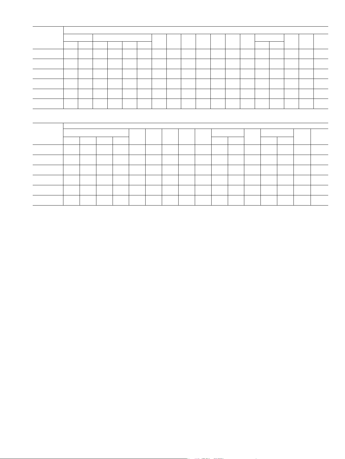
15
MODELS
OPTIONS
OPT 1 OPT 2
OPT
3
OPT
3X
OPT
4
OPT
5
OPT
6
OPT
7
OPT
8
OPT 9
OPT
10
OPT
12
OPT
14
1A 1B 2A 2B 2C 2E 9K 9V
MG3691C
• • • •
9,11
•
13
•
13
•
1
•
1
• •
2,12
•
8
•
8
•
3
• •
MG3692C
• • • •
13
•
13
•
1
•
1
• •
2,12
•
8
•
8
•
3
• •
MG3693C
• • • •
13
•
13
•
1
•
1
• •
2,12
•
8
•
8
•
3
• •
MG3694C
• • • •
13
•
13
•
1
•
1
• •
2,12
•
8
•
8
•
3
• •
MG3695C
• • • •
13
•
13
•
1
•
1
• •
8
•
8
•
3
• •
MG3697C
• • • •
13
•
13
•
1
•
1
• •
8
•
8
•
3
• •
MODELS
OPTIONS
OPT 15
OPT
16
OPT
17
OPT
18
OPT
20
OPT
22
OPT 26
OPT
27
OPT 28
OPT
98
OPT
99
15A 15B 15C 15D 26A 26B 28A 28B
MG3691C
•
12
• •
10
•
2,12
•
9
•
5,11
• •
6
•
7
• •
MG3692C
•
12
• •
10
•
2,12
•
9
•
5
• •
6
•
7
• •
MG3693C
•
12
• •
10
•
2,12
•
5
• •
6
•
7
• •
MG3694C
•
12
• •
10
•
2,12
•
5
• •
6
•
7
• •
MG3695C
•
12
• •
10
•
12
•
5
• •
6
•
7
• •
MG3697C
•
12
• •
10
• •
5
• •
6
•
7
• •
Footnote 1 Options 4 and 5 CAN NOT be ordered together
Footnote 2 Options 7 and 18 CAN NOT be ordered together
Options 7 and 20 CAN NOT be ordered together
Footnote 3 Option 10 CAN ONLY be ordered with either Options 27 or 28
Footnote 5 Option 22 CAN ONLY be ordered with either Options 4 or 5
Option 22 CAN NOT be ordered with Option 20
Footnote 6 Option 27 CAN ONLY be ordered with either Options 12, 14 or 26
(in any combination)
Footnote 7 Option 28 CAN NOT be ordered along with either Options 12, 14, 26, or 27
Footnote 8 Option 8 CAN NOT be ordered along with Option 9
Footnote 9 Option 20 CAN NOT be ordered with Option 2E, Option 7,
Option 15 or Option 22
Footnote 10 Option 17 CAN ONLY be ordered with either Option 1A or 1B
Footnote 11 Option 2E CAN NOT be ordered with Option 22
Footnote 12 Option 18 CAN NOT be ordered with Option 15 or 7,
Option 15 CAN NOT be ordered with Option 20
Footnote 13 Option 3 CAN NOT be ordered with Option 3X and visa versa.
MG3690C OPTION CONFIGURATION GUIDE – Important: Please see footnotes where applicable