Printer 600 Paste Dispenser System.pdf
3$67(' ,63(16(56 <67(0 02'8/( 29(59,(: Chapter Issue 2 Jul 02 Technical Reference Manual 10.1 CHAPTER 10 P ASTE DISPENSER SYSTEM MODULE OVERVIEW Purpose The optional p aste dispens er is only utili zed wh…

3$67(',63(16(56<67(0
02'8/(29(59,(:
Chapter Issue 2 Jul 02 Technical Reference Manual 10.1
CHAPTER 10 PASTE DISPENSER SYSTEM
MODULE OVERVIEW
Purpose The optional paste dispenser is only utilized when the machine is fitted with
squeegees. The purpose of the paste dispenser is to dispense a precise
quantity of solder paste which is equal in length to the print width and along a
line which is calculated from the print stroke start position and the size of the
board.
The paste is dispensed by applying pneumatic pressure to a paste cartridge
installed in a special holder. The paste dispenser is mounted on a pivot which
is driven by a dc motor to the vertical position for dispensing paste.
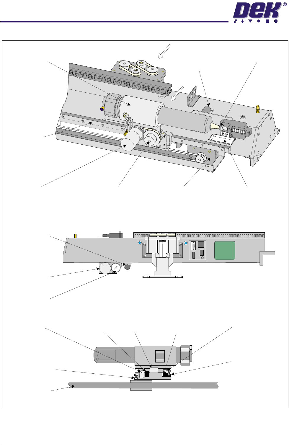
Elements The paste dispense is a stepper driven system comprising:
• Paste Dispense Carriage
• Paste Carriage Stepper Motor
• Cartridge Horizontal (Up) Sensor
• Cartridge Vertical (Down) Sensor
• Paste Dispenser
• Cartridge Empty Sensor
• Paste Dispense Carriage Bearing
• Paste Carriage Home Sensor
• Cartridge Tilt Motor
Operation The paste dispenser mechanism is driven along the horizontal rail of the paste
dispense carriage, which is mounted on the print carriage. This drive together
with the movement of the print carriage enables the paste dispenser to be
moved parallel to the squeegee blades in order to dispense paste anywhere on
the screen.
The system can control the quantity of paste dispensed in the following ways:
Machine programmable:
• Dispense speed
• Dispense rate
• Start and stop positions
User Setting:
• Dispense air pressure
• Nozzle size
The paste dispense system uses 1kg paste cartridges. 500g paste cartridges
may be used with the aid of an additional spacer.
3$67(',63(16(56<67(0
02'8/(29(59,(:
10.2 Technical Reference Manual Chapter Issue 2 Jul 02
Figure 10-1 Paste Dispense Overview
Paste Dispense
Carriage
Paste Carriage
Stepper Motor
Paste Drip
Tray
Paste Dispenser
Cartridge Tilt
Motor
Paste Dispense
Clutch
Cartridge
Empty Sensor
Paste Seal
Paste Dispenser Rear View
Cartridge Horizontal
(Up) Sensor
Paste Carriage
Home Vane
Cartridge
(Down) Sensor
Vertical
Paste Dispense
Carriage
Cartridge
(Up) Vane
Horizontal
Cartridge
(Up) Hard Stop
Horizontal
Cartridge
(Down) Hard Stop
Vertical
Cartridge Vertical
(Down) Vane
View on Arrow B
Paste Carriage
Stepper Motor
Paste Dispense
Pressure Gauge
Paste Dispense
Regulator
View on Arrow A
A
B
3$67(',63(16(56<67(0
(/(&75,&$/6&+(0$7,&
Chapter Issue 2 Jul 02 Technical Reference Manual 10.3
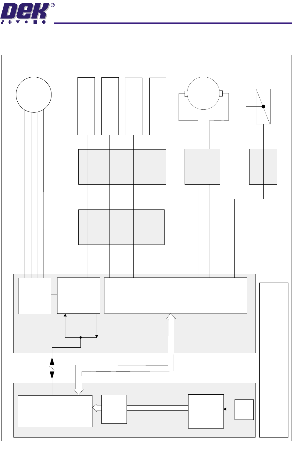
ELECTRICAL SCHEMATIC
Machine Controller
Channel 1 Motor O/P B-
Channel 1 Motor O/P B+
Channel 1 Motor O/P A-
Channel 1 Motor O/P A+
Step/
Dir-7
MUX
Home
Dual
Stepper
X6
100 Way
Machine PC
CAN Bus
NextMove
ISA 10
Processor
ISA 3
+12V
PSU
RS232
Expansion
I
S
A
B
u
s
Breakout
Board E
Breakout
Board C
Breakout
Board B
Breakout
Board D
TOTEM 4
IN5
IN3
DIG IN14
IN4
TOTEM 5
SOURCE 6
Paste
Dispense
Solenoid
16SOL05
Manual Operation
Multiplexer
X1
Paste
Carriage
Stepper
Motor
9M8
9M9
Cartridge
Tilt
Motor
Paste Carriage
Home Sensor
9SE12
Cartridge Vertical
(Down) Sensor
9SE14
Cartridge Horizontal
(Up) Sensor
9SE13
Cartridge Empty
Sensor
9SE15
MultiMove
X12
NOTE
The CAN Bus forms part of the 100 way connection
between the Machine PC and Controller enclosures