Printer 600 Paste Dispenser System.pdf - 第9页
3$67(' ,63(16(56 <67(0 6(48 (1&(6 Chapter Issue 2 Jul 02 Technical Reference Manual 10.9 3. The p aste dispenser is dri ven to the paste st art position. 4. Pneumatic press ure is appli ed to the past e dis…
3$67(',63(16(56<67(0
6(48(1&(6
10.8 Technical Reference Manual Chapter Issue 2 Jul 02
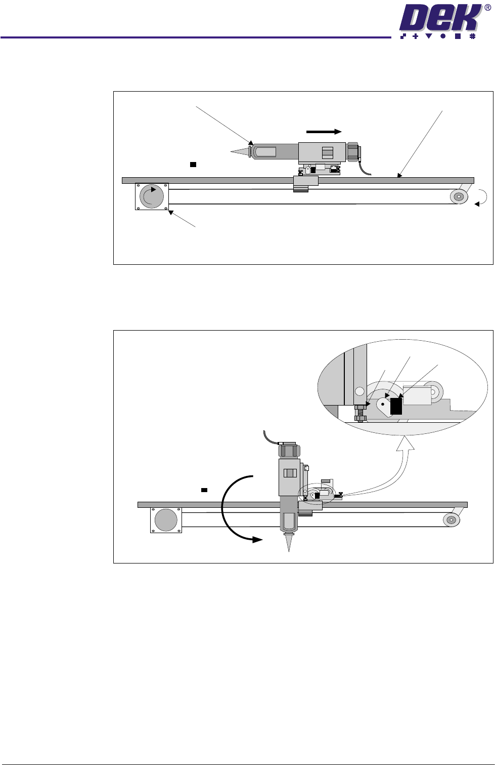
1. The paste dispenser is driven to the centre by the paste carriage stepper
motor.
2. The dispensing unit is rotated to the vertical position by the tilt motor, via a
slipping clutch. The vertical position is set by the down adjustable hard stop.
The vane enters the sensor stopping the tilt motor.
Paste Carriage (Viewed from Front of machine)
Paste Carriage Stepper Motor
Paste Dispenser Paste Carriage Rail
Vane
Hard
Stop
Sensor
3$67(',63(16(56<67(0
6(48(1&(6
Chapter Issue 2 Jul 02 Technical Reference Manual 10.9
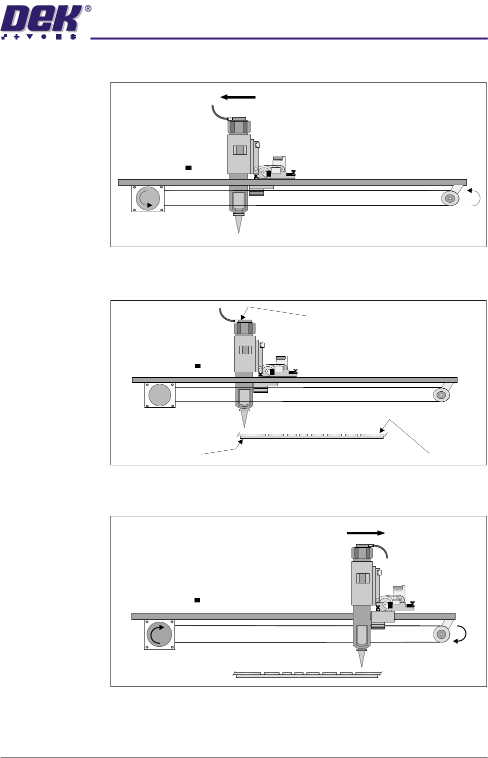
3. The paste dispenser is driven to the paste start position.
4. Pneumatic pressure is applied to the paste dispenser cartridge. Paste is
applied to the stencil.
5. The paste dispenser is driven across the screen to the paste stop position,
dispenser movement is halted and pneumatic pressure is removed.
Board
Stencil
Pneumatic Connection
3$67(',63(16(56<67(0
6(48(1&(6
10.10 Technical Reference Manual Chapter Issue 2 Jul 02
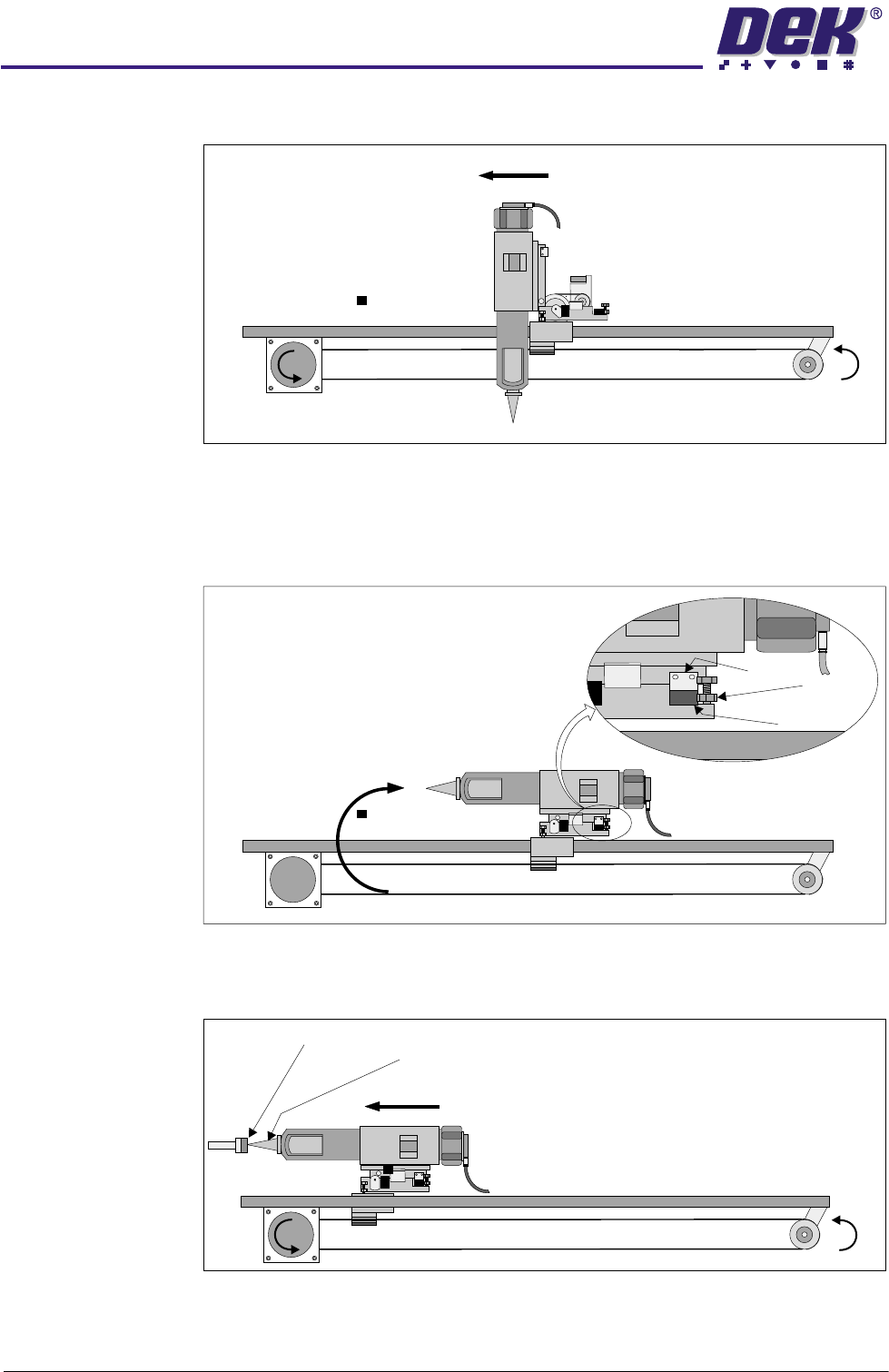
6. The paste dispenser is driven to the centre.
7. The dispensing unit is rotated to the horizontal position, as set by the up
adjustable hard stop. The vane enters the sensor stopping the tilt motor.
During rotation a series of motor reversals is carried out to remove excess
paste from the nozzle.
8. The paste dispenser is driven to the home position. The nozzle is sealed
against the spring loaded paste seal.
Vane
Stop
Sensor
Paste Seal
Nozzle