Printer 600 Paste Dispenser System.pdf - 第4页
3$67(',6 3(16(56< 67(0 0(&+$1 ,&$/'(7$ ,/ 10.4 Technical Reference Manual Chapter I ssue 2 Jul 02 MECHANICAL DET AIL Cartridge T ilt Mechanism The cartridge is ti lted by a moving coil motor and g…
3$67(',63(16(56<67(0
(/(&75,&$/6&+(0$7,&
Chapter Issue 2 Jul 02 Technical Reference Manual 10.3
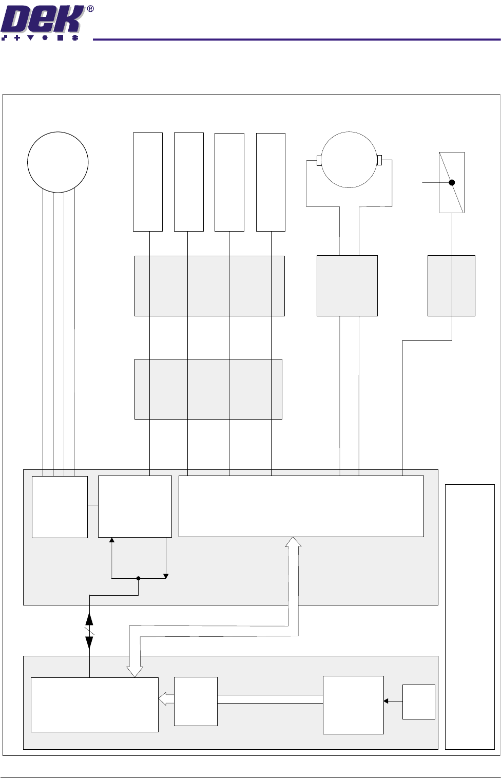
ELECTRICAL SCHEMATIC
Machine Controller
Channel 1 Motor O/P B-
Channel 1 Motor O/P B+
Channel 1 Motor O/P A-
Channel 1 Motor O/P A+
Step/
Dir-7
MUX
Home
Dual
Stepper
X6
100 Way
Machine PC
CAN Bus
NextMove
ISA 10
Processor
ISA 3
+12V
PSU
RS232
Expansion
I
S
A
B
u
s
Breakout
Board E
Breakout
Board C
Breakout
Board B
Breakout
Board D
TOTEM 4
IN5
IN3
DIG IN14
IN4
TOTEM 5
SOURCE 6
Paste
Dispense
Solenoid
16SOL05
Manual Operation
Multiplexer
X1
Paste
Carriage
Stepper
Motor
9M8
9M9
Cartridge
Tilt
Motor
Paste Carriage
Home Sensor
9SE12
Cartridge Vertical
(Down) Sensor
9SE14
Cartridge Horizontal
(Up) Sensor
9SE13
Cartridge Empty
Sensor
9SE15
MultiMove
X12
NOTE
The CAN Bus forms part of the 100 way connection
between the Machine PC and Controller enclosures
3$67(',63(16(56<67(0
0(&+$1,&$/'(7$,/
10.4 Technical Reference Manual Chapter Issue 2 Jul 02
MECHANICAL DETAIL
Cartridge Tilt
Mechanism
The cartridge is tilted by a moving coil motor and gearbox which is driven from
MultiMove X12 in the machine controller.
Two channels are used to allow bi-directional drive. Positional control of the
cartridge tilt mechanism is by the use of cartridge horizontal (up) and cartridge
vertical (down) sensors, which feed via MultiMove X12 and the CAN bus to the
NextMove card in the PC, which in turn controls the MultiMove X12 drive output
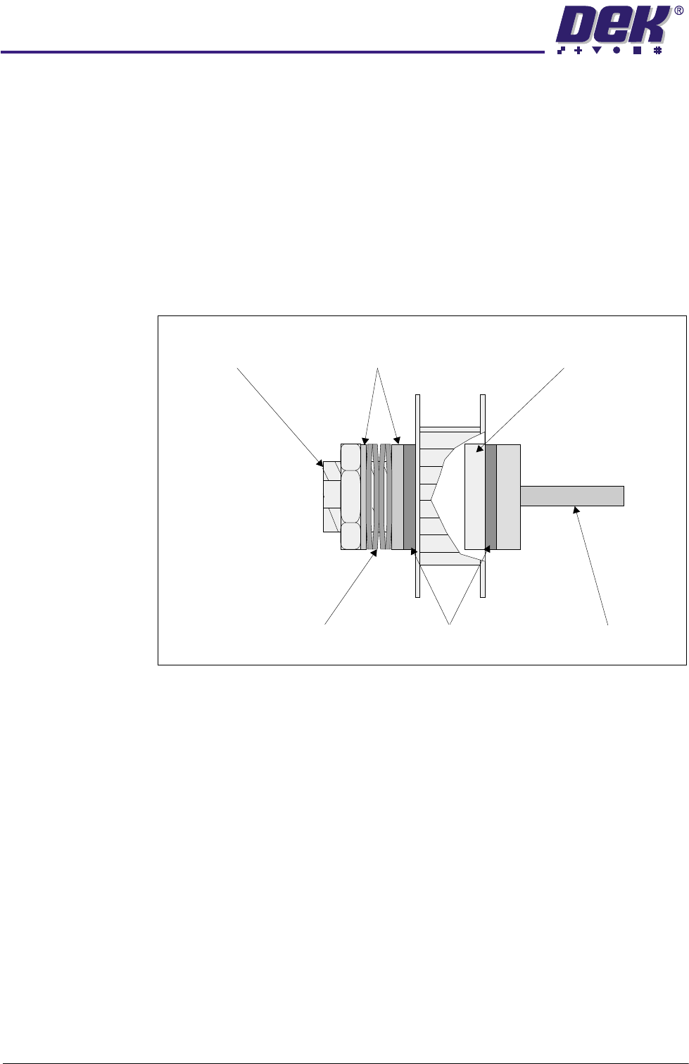
to the cartridge tilt motor. On its own this system would not position the cartridge
repeatedly so hard stops are provided for the cartridge horizontal (up) and
cartridge vertical (down) positions and the motor drives the unit against these
via a clutch mechanism.
Figure 10-2 Clutch Assembly
Cut-away showing
Bush within
Pulley recess
Friction Plate
Spindle
(with 1 flat)
Cup Washers
Washers
(with 2 flats)
Bolt
(with 2 flats)
3$67(',63(16(56<67(0
'5,9(6$1'6(16256
Chapter Issue 2 Jul 02 Technical Reference Manual 10.5
DRIVES AND SENSORS
Motors
Sensors
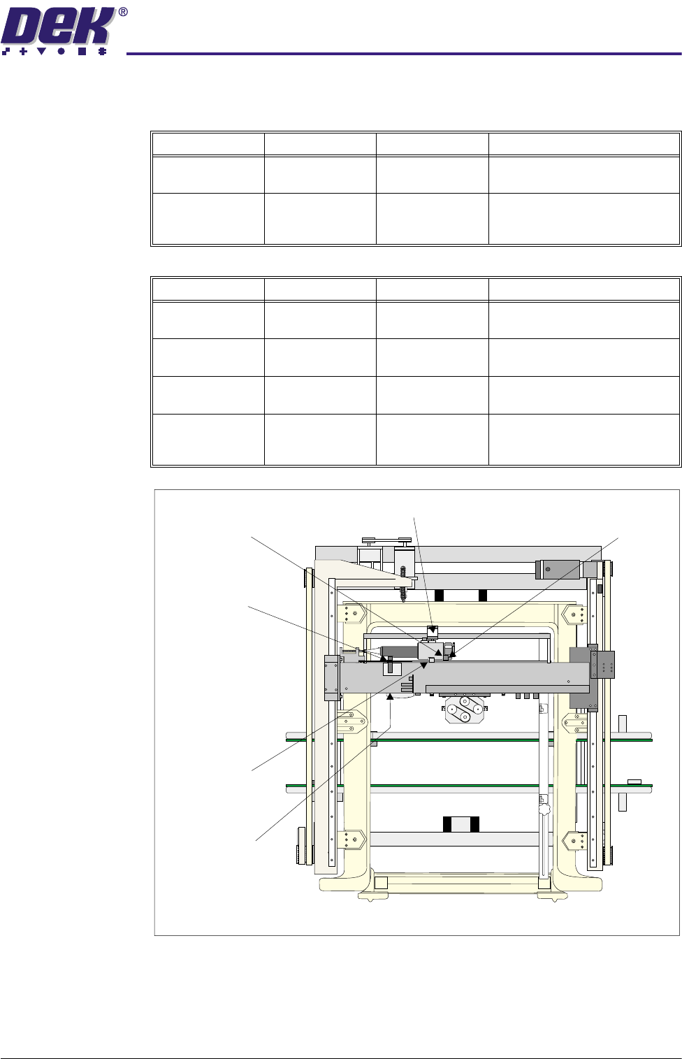
Figure 10-3 Drives and Sensors Location
Name Type Control Card Functional Description
Paste Carriage
Stepper Motor
Stepper Motor
9M8
Dual Stepper X6 Drives the paste dispenser along
the X axis to dispense paste.
Cartridge Tilt
Motor
dc Moving Coil
Motor 9M9
MultiMove X12 Drives the paste dispenser down
to dispense paste and up to
home the dispenser.
Name Type Control Card Functional Description
Paste Carriage
Home Sensor
Hall Effect 9SE12 Multiplexer X1 Determines the home position
for the paste dispense carriage.
Cartridge Empty
Sensor
Proximity 9SE15 MultiMove X12 Determines when the paste car-
tridge is empty.
Cartridge Vertical
(Down) Sensor
Hall Effect 9SE14 MultiMove X12 Determines the down position for
the paste dispenser
Cartridge Hori-
zontal (Up) Sen-
sor
Hall Effect 9SE13 MultiMove X12 Determines the up position for
the paste dispenser.
Printhead Plan View
(Covers removed)
Cartridge Horizontal
(Up) Sensor
Paste Carriage
Home Sensor
Paste Carriage
Stepper Motor
(Beneath)
Cartridge
Empty Sensor
Cartridge Tilt Motor
Cartridge Vertical
(Down) Sensor