Printer 600 Paste Dispenser System.pdf - 第11页
3$67(' ,63(16(56 <67(0 6(48 (1&(6 Chapter Issue 2 Jul 02 Technical Reference Manual 10.11 NOTE 1. The pa ste start and pa ste stop posit ions are held in the product file. The default positions are set by t…
3$67(',63(16(56<67(0
6(48(1&(6
10.10 Technical Reference Manual Chapter Issue 2 Jul 02
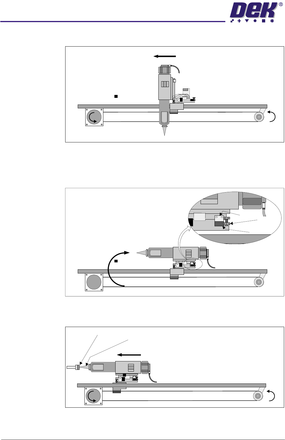
6. The paste dispenser is driven to the centre.
7. The dispensing unit is rotated to the horizontal position, as set by the up
adjustable hard stop. The vane enters the sensor stopping the tilt motor.
During rotation a series of motor reversals is carried out to remove excess
paste from the nozzle.
8. The paste dispenser is driven to the home position. The nozzle is sealed
against the spring loaded paste seal.
Vane
Stop
Sensor
Paste Seal
Nozzle

3$67(',63(16(56<67(0
6(48(1&(6
Chapter Issue 2 Jul 02 Technical Reference Manual 10.11
NOTE
1. The paste start and paste stop positions are held in the product file. The
default positions are set by the board length. These positions can be
customized in the edit data menu.
2. An alternate paste dispense can be set to apply paste to either the centre
50% or end 25% of the standard dispense. The ratio of alternate to standard
dispenses can also be set.
3. The speed of the paste dispenser, driven between the paste start and paste
stop positions, is programmable and determines the volume of paste
applied.
4. The paste dispense position can be set to either the front or rear of the
image.
5. Paste can be dispensed with a board loaded and held at print height. This
overcomes the problem of paste dropping from the squeegees or paste
dispenser onto and through the image.
3$67(',63(16(56<67(0
$'-8670(176$1'6(77,1*6
10.12 Technical Reference Manual Chapter Issue 2 Jul 02
ADJUSTMENTS AND SETTINGS
Paste Carriage
Home Sensor
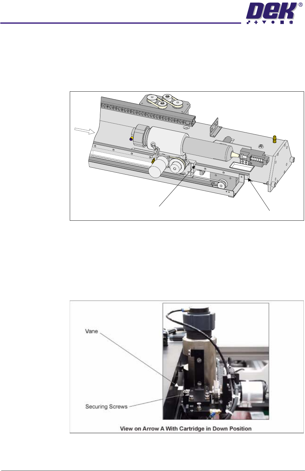
1. In Diagnostics select Paste Dispense System.
2. Select Carriage Home.
3. Check that the distance from the edge of the paste carriage bearing block
to the end of the paste carriage THK rail is 175mm -177mm.
4. If adjustment is necessary, select Drive Cartridge Down.
5. Slacken the two paste carriage home Hall effect vane securing screws,
using a 2.5mm Allen key and adjust the vane. Tighten the two securing
screws.
6. Repeat Steps 2 - 5 until the setting is achieved.
7. Ensure that the vane does not foul the sensor as it passes through the Hall
effect.
A
Edge of
Bearing Block
End of THK Rail