00193730-04.pdf - 第29页
Retrofit instructions Splice Detection Basic Packa ge + Table Controller SIPLACE HF-series 08/2005 Edition 29 : Connect sockets #2 and #4 using the cable provided (03006 409-01) (Fig. above). : Now refit the complete dev…
Retrofit instructions Splice Detection Basic Package + Table Controller SIPLACE HF-series
08/2005 Edition
28
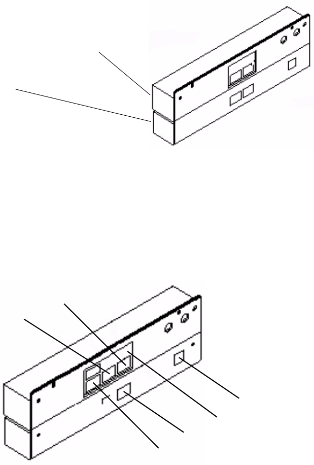
: Connect the communication interface and table controller (TC) to one another. The screws that
protrude from the communication interface should fit into the recesses in the table controller
case. If necessary, loosen the screws on the back of the table controller slightly (Fig. 6 - 2), fit
the communication interface and then tighten the screws once more.
2
Abb. 2.10 - 2 Communication interface and table controller (TC) connected to one another
: Plug in and secure the connectors that you removed when dismantling the communication in-
terface (Fig. 6 - 3).
: Plug the communication connector (9-pin) into socket #1 and the power supply connector (3-
pin) into socket #3. Screw the green/yellow grounding cable to the back panel of the TC using
a hexagon socket head screw.
2
Abb. 2.10 - 3 Whole unit showing the connector and ground positions
2
2
2
Communication unit
TC
#5
GND
#4
#3
#2
#1
Retrofit instructions Splice Detection Basic Package + Table Controller SIPLACE HF-series
08/2005 Edition
29
: Connect sockets #2 and #4 using the cable provided (03006409-01) (Fig. above).
: Now refit the complete device to the bed of the changeover table.
2
2
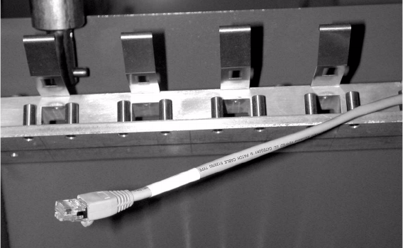
The CAT5 data cable, part no.: 03001303-01 (see picture), is fixed inside the machine using cable
ties. 2
: Plug the existing CAT5 data cable into socket #5. Then fix it to the bottom of the case using
cable clips.
: Push the component feeder table back into the machine.
2
Retrofit instructions Splice Detection Basic Package + Table Controller SIPLACE HF-series
08/2005 Edition
30
2.8 Adapter (third tape reel)
2.8.1 Content of retrofit kit (Part no.:00119642-01)
Qty Designation Part no.:
- 1 Left bracket, complete 03012611-01
- 1 Right bracket, complete 03012647-01
- Assembly materials
2.8.2 Installation
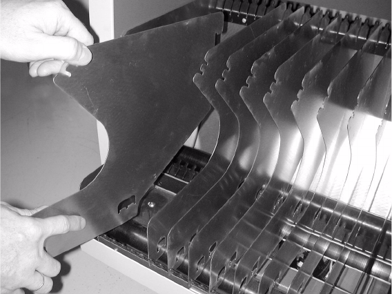
: Open the protective cover.
: Dock the component trolley out of the placement machine.
: Take the tape reels from the tape reel container.
: Take the outer tape separators (left and right) out of the component trolley.
2
2
2
2
2
2
2