00193730-04.pdf - 第35页
Retrofit instructions Splice Detection Basic Packa ge + Table Controller SIPLACE HF-series 08/2005 Edition 35 : Secure the cables with cable ties. : Connect the power supply cable to the terminals shown in the picture. 2…
Retrofit instructions Splice Detection Basic Package + Table Controller SIPLACE HF-series
08/2005 Edition
34
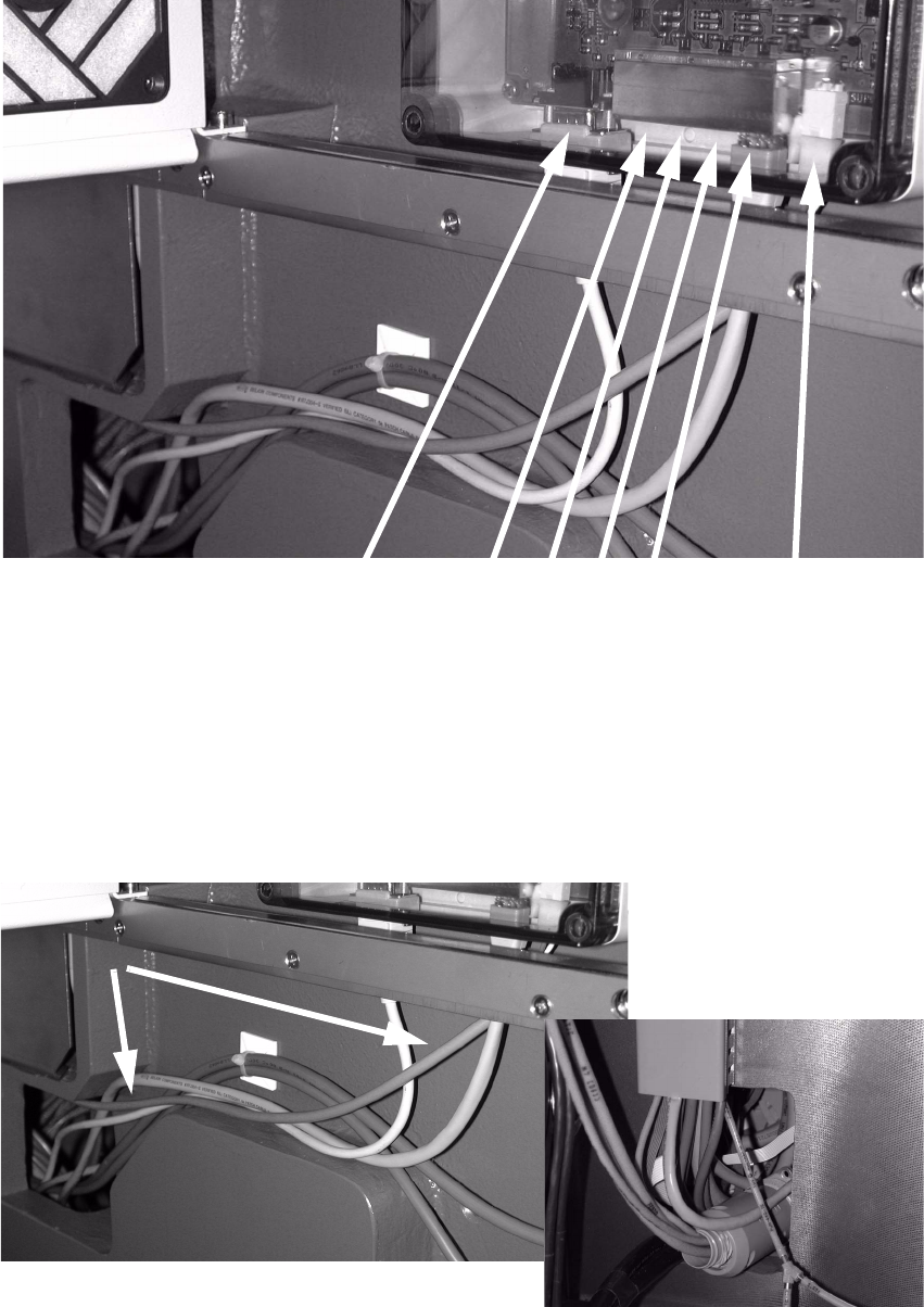
: Plug the connectors into the communication interface (see picture below).
2
: Run the six cables (as shown in the picture above) into the opening in the machine base.
: Run the power supply cable.
2
Power supply
connection
Table
1 2 3 4
Connecting cables
CAT5 cables)
to component trolley 1-4
Connecting cable
to 03007804
Retrofit instructions Splice Detection Basic Package + Table Controller SIPLACE HF-series
08/2005 Edition
35
: Secure the cables with cable ties.
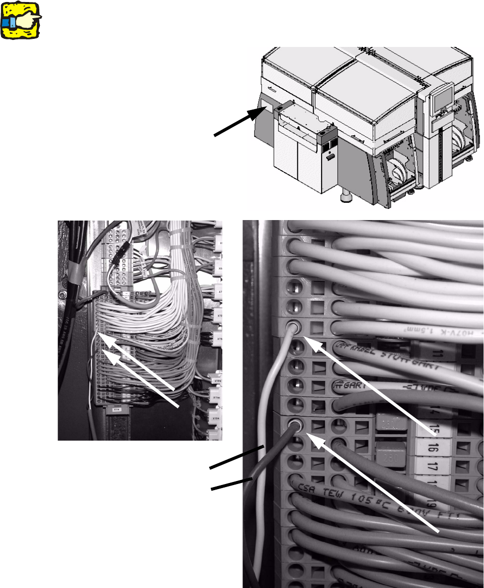
: Connect the power supply cable to the terminals shown in the picture.
2
At the clamping fields of newer machines possibly only one connection is free.
Measure the connection before connecting the cable to avoid damage caused by false voltage!2
2
White = GND
Brown = +15V
Position of the terminals
Retrofit instructions Splice Detection Basic Package + Table Controller SIPLACE HF-series
08/2005 Edition
36
: To pull the four cables to the component trolley through the placement machine, you can first
pull a relatively rigid wire through the machine frame, and tie the cables to it.
2
2
: Then pull the cable through the machine frame using the wire.
2
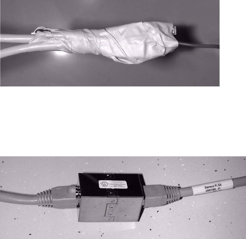
: Connect the cable (part no.: 03001300-01) to the cable plugged into the component trolley
using the coupling.
2
2
2
2
2
2
2
2