IPC-2223-Design-Standard-for-Flex-and-Rigid-Flex-Circuits.pdf - 第10页
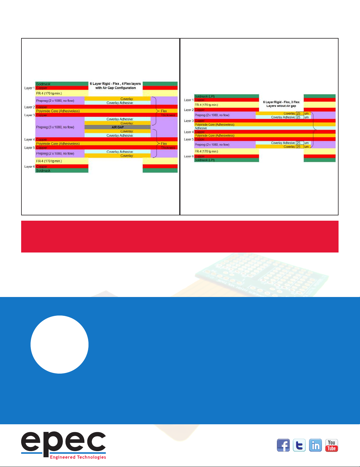
“ DEFINE AIR GAP CONSTRUCTION REQUIREMENTS IN THE F ABRICA TION DRA WING NO TES AND MA TERIAL ST A CKUP Examples of both air gap and non-air gap constructions.
Important Element
#4
Rigid-Flex Air Gap
Some designs require higher ex layer counts to meet the circuit routing
requirements. Minimizing the ex layer count to 1 or 2 layers has the
multiple advantages of improved exibility, tighter bend capabilities, and
reduced cost but is not always achievable in higher density designs. For 3
ex layers or more IPC recommends, whenever possible, conguring the
ex layers as independent pairs rather than laminating all the ex layers
together into one stack. This conguration is referred to as an “air gap”
construction due to the open space between ex layers. The recommended
air gap construction eliminates the all ex adhesives within the rigid
sections and the associated via hole reliability concerns.
IPC 2223 does allow laminating all ex layers together for designs with two
sided shielding or stripline impedance control requirements. This is with the
recommendation that the use of adhesive layers be minimized and is not to
exceed 10% of the total ex thickness.
An added benet of the air gap construction is signicantly improved
exibility. The ex pairs act individually when bent and provide almost as
much exibility as a two layer only conguration
“
DEFINE AIR GAP CONSTRUCTION
REQUIREMENTS IN THE FABRICATION
DRAWING NOTES AND MATERIAL STACKUP
Examples of both air gap and non-air gap constructions.
Minimum Bend Radius Capabilities
A key element to a successful design is ensuring the ex construction
meets the bend requirements. The bend capability of a ex section is
dependent upon the materials and material thicknesses used and cannot
be impacted by the manufacturing process. IPC 2223 provides minimum
bend recommendations for both static “one-time” or “bend to t” as well as
“dynamic” or “innite bend” applications. These dier signicantly in the
allowable layer count, minimum bend capability, and the allowable copper
type - either electrodeposited or rolled annealed. The minimum bend
radius can be calculated or is commonly dened as a multiplier of the ex
thickness. Bend to t applications vary from 6x to 20x or greater depending
upon layer count. Dynamic applications are typically 100x with a maximum
of two layers.
IPC 2223 also allows, with specic guidelines, for a ex to be bent and
creased with a zero bend radius. This is limited to very thin one and two
layer constructions with the added stipulation that once the ex is creased
it cannot be unfolded. A PSA, pressure sensitive adhesive/doubled sided
tape, is often added in the fold area to permanently ax the ex and ensure
that it is not inadvertently unfolded.
Many designs call out for a specic number of bend cycles. For these
applications that fall between IPC’s guidelines, we recommend getting
material and construction input from the ex circuit supplier and cycle
testing the ex circuits as part of the design approval process.
Important Element
#5