IPC-2223-Design-Standard-for-Flex-and-Rigid-Flex-Circuits.pdf - 第4页
Image (left) via hole location meets IPC r equirements. Image (right) is in violation. “ VIA AND PTH SP A CING T O THE RIGID/FLEX TRANSITION IS CRITICAL T O FINISHED P AR T RELIABILITY
Important Element
#1
Rigid-Flex Transition Via Keep Out Areas
A key element, impacting the reliability of rigid-ex circuits, is the location of
any plated vias or holes in relation to the transition from a rigid section to a
exible section. This is covered in Sec. 5.2.2.3. This area of a design has
the unique requirement that the polyimide coverlays, which encapsulate
the exible areas, must engage into the rigid areas by a small distance to
ensure that they are captured by the rigid area lamination process. The
coverlays are laminated to the ex surface with an adhesive, either acrylic
or epoxy based. These adhesives have a very high coecient of thermal
expansion. If vias are drilled through the adhesive they are subjected to
stresses caused by the thermal expansion and contraction of the adhesive.
This creates a signicant reliability concern as the plating within the via
can crack when subjected to assembly reow temperatures and in the eld
temperature uctuations. IST, interconnect stress testing, has proven this
can occur.
IPC 2223 species a minimum distance of 0.125” but this is considered
generous. Most manufacturers can meet the intent of not allowing vias
to be drilled through the coverlay adhesive with much smaller keep out
distances. Such a larger distance as specied by IPC can also cause
circuit layout challenges on high density designs. Epec’s standard minimum
spacing requirement is 0.050” as measured from the edge of the hole and
some designs may allow for 0.040”.
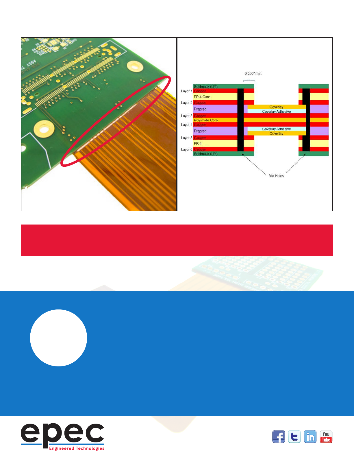
Image (left) via hole location meets IPC requirements. Image (right) is in violation.
“
VIA AND PTH SPACING TO THE RIGID/FLEX
TRANSITION IS CRITICAL TO FINISHED PART
RELIABILITY
Rigid-Flex Selective Coverlay Construction
Evolving technology and design complexity, smaller VIA holes and RoHS
assembly temperatures necessitated a change in the construction method
of the ex area coverlays. Previous methods applied the coverlays
throughout the entire design, including rigid areas. This old method resulted
in all vias and PTH holes being drilled through the coverlay adhesives. As
mentioned in the previous section, this exposes the vias to the thermal
expansion issue of the adhesive and incurs the associated reliability issues.
IPC Section 5.2.2.2 denes that coverlays are to be applied “selectively”
to the ex areas only with only a small distance of engagement into the
rigid sections. This method has the added benet that the coverlays and
adhesives are not a component in the rigid area lamination which results
in a stronger lamination. This method does have a slight cost impact as
the coverlays require an additional machining process to remove the
material from the rigid areas. It is important to dene a selective coverlay
construction in the data set to ensure the nished parts meet IPC 2223.
Important Element
#2