IPC-2223-Design-Standard-for-Flex-and-Rigid-Flex-Circuits.pdf - 第9页
Important Element #4 Rigid-Flex Air Gap Some designs require higher ex layer counts to meet the circuit routing requirements. Minimizing the ex layer count to 1 or 2 layers has the multiple advantages of improved exib…
“
SPECIFY ADHESIVELESS FLEX CORE BY THE
IPC SPECIFICATION IN THE DRAWING NOTES
AND GRAPHICALLY IN THE MATERIAL STACKUP
IN THE FABRICATION DRAWING
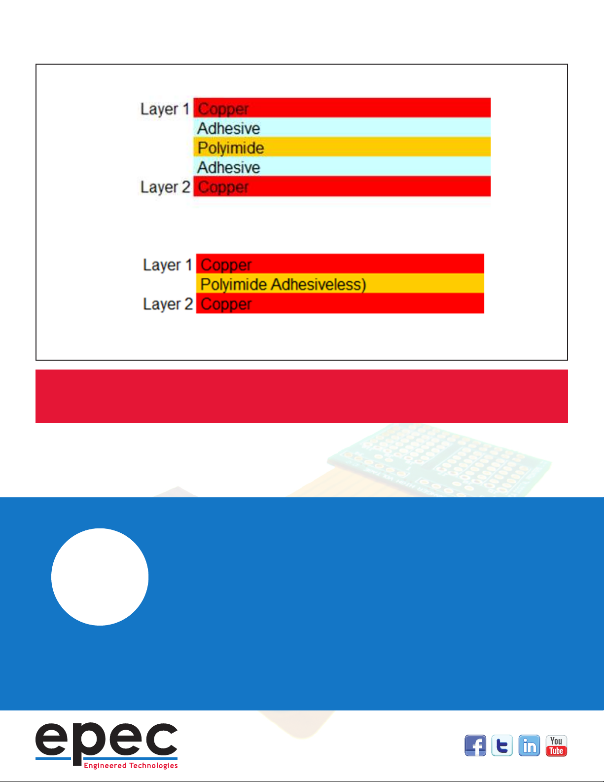
Adhesive flex core (top), adhesiveless flex core (bottom).
Important Element
#4
Rigid-Flex Air Gap
Some designs require higher ex layer counts to meet the circuit routing
requirements. Minimizing the ex layer count to 1 or 2 layers has the
multiple advantages of improved exibility, tighter bend capabilities, and
reduced cost but is not always achievable in higher density designs. For 3
ex layers or more IPC recommends, whenever possible, conguring the
ex layers as independent pairs rather than laminating all the ex layers
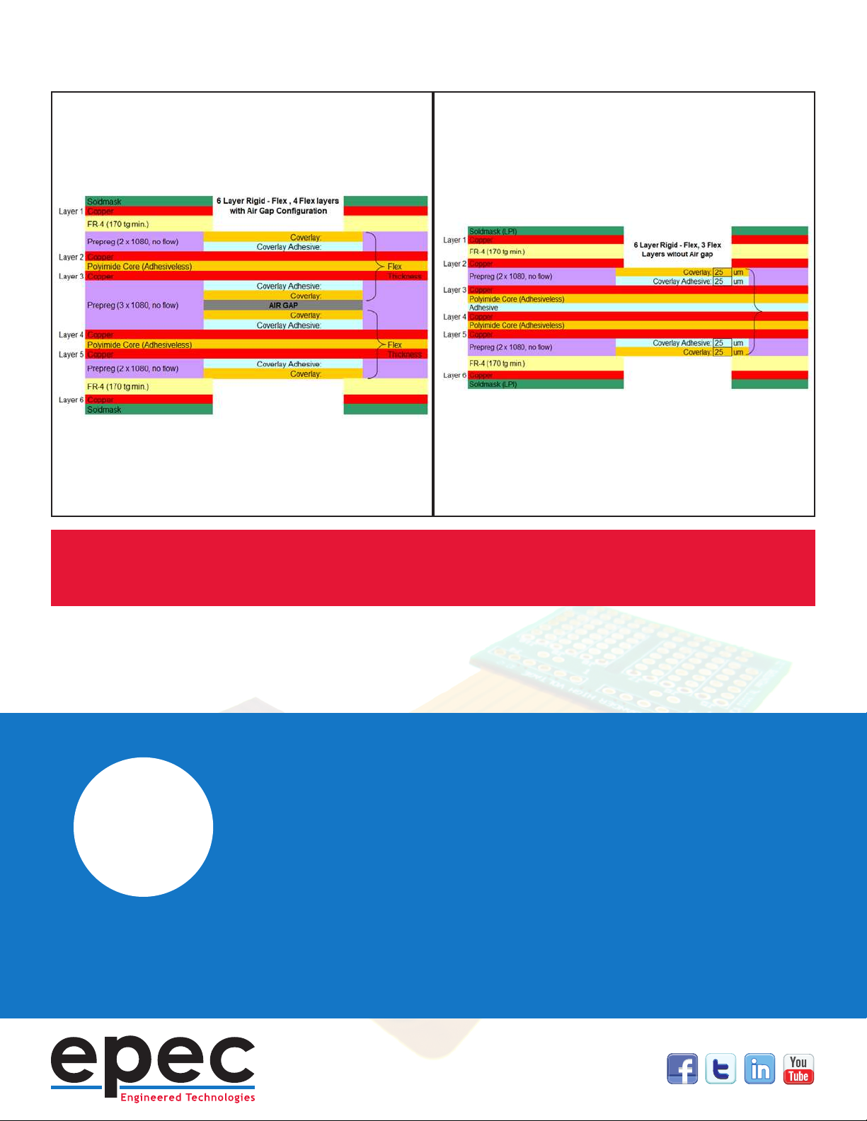
together into one stack. This conguration is referred to as an “air gap”
construction due to the open space between ex layers. The recommended
air gap construction eliminates the all ex adhesives within the rigid
sections and the associated via hole reliability concerns.
IPC 2223 does allow laminating all ex layers together for designs with two
sided shielding or stripline impedance control requirements. This is with the
recommendation that the use of adhesive layers be minimized and is not to
exceed 10% of the total ex thickness.
An added benet of the air gap construction is signicantly improved
exibility. The ex pairs act individually when bent and provide almost as
much exibility as a two layer only conguration
“
DEFINE AIR GAP CONSTRUCTION
REQUIREMENTS IN THE FABRICATION
DRAWING NOTES AND MATERIAL STACKUP
Examples of both air gap and non-air gap constructions.