IPC-2223-Design-Standard-for-Flex-and-Rigid-Flex-Circuits.pdf - 第12页
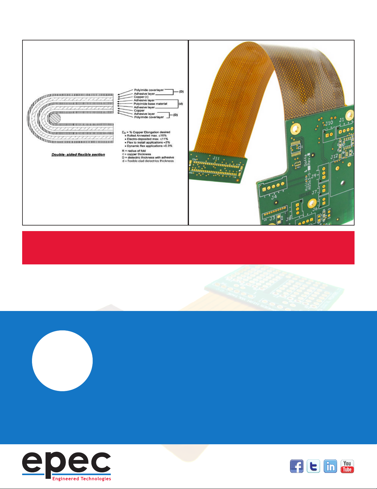
“ MEETING THE DESIGN BEND REQUIREMENTS RELIABL Y IS A KEY ELEMENT T O A SUCCESSFUL DESIGN. EVEN IF THE P AR T IS BEING BENT ONE TIME ONL Y . Side view cutaway of a bent flex cir cuit and the impact on specific layers.
Minimum Bend Radius Capabilities
A key element to a successful design is ensuring the ex construction
meets the bend requirements. The bend capability of a ex section is
dependent upon the materials and material thicknesses used and cannot
be impacted by the manufacturing process. IPC 2223 provides minimum
bend recommendations for both static “one-time” or “bend to t” as well as
“dynamic” or “innite bend” applications. These dier signicantly in the
allowable layer count, minimum bend capability, and the allowable copper
type - either electrodeposited or rolled annealed. The minimum bend
radius can be calculated or is commonly dened as a multiplier of the ex
thickness. Bend to t applications vary from 6x to 20x or greater depending
upon layer count. Dynamic applications are typically 100x with a maximum
of two layers.
IPC 2223 also allows, with specic guidelines, for a ex to be bent and
creased with a zero bend radius. This is limited to very thin one and two
layer constructions with the added stipulation that once the ex is creased
it cannot be unfolded. A PSA, pressure sensitive adhesive/doubled sided
tape, is often added in the fold area to permanently ax the ex and ensure
that it is not inadvertently unfolded.
Many designs call out for a specic number of bend cycles. For these
applications that fall between IPC’s guidelines, we recommend getting
material and construction input from the ex circuit supplier and cycle
testing the ex circuits as part of the design approval process.
Important Element
#5
“
MEETING THE DESIGN BEND REQUIREMENTS
RELIABLY IS A KEY ELEMENT TO A
SUCCESSFUL DESIGN. EVEN IF THE PART IS
BEING BENT ONE TIME ONLY.
Side view cutaway of a bent flex circuit and the impact on specific layers.
Important Element
#6
Strain Relief Fillets
A strain relief llet is dened as a exible bead, typically epoxy based,
applied to the transition line from a rigid area to a ex area. This forces the
ex to bend gradually and prevents it from being bent tightly against the
rigid area which could damage the part.
IPC calls out for a minimum 0.010” height dierence between the rigid area
and the ex layers to allow enough space for the bead without it extending
above the surface level of the rigid area. Strain reliefs requirements are
dened in the fabrication drawing. A minimum and maximum horizontal
dimension need to be dened as is commonly 0.040” to 0.100” to allow
for manufacturing tolerances and the material ow properties. The most
commonly used material is Eccobond 45/15 mixed in the exible formula
ratio. Others can be used but will need to be applied after assembly if they
cannot withstand assembly reow temperatures.
Many designs do not require or cannot utilize strain reliefs. Designs
with very short ex lengths may result in the strain reliefs limiting the
bend capabilities. The added cost may not be justied for relaxed bend
applications. Reliefs should also be limited to the rigid to ex transitions
that require it and not applied globally.