00198351-01_AI_Location 2 Upgrade Kit_E by SIPLACE_en.pdf - 第13页
Assembly Instructions E by SIPLACE Location 2 Upgrade Kit 04/2017 2 Installation of Location 2 Upgrade Kit 2.1 Preparing Steps 13 2 Installation of Location 2 Upgrade Kit In this chapter you will find the instructions fo…

1 Introduction
1.4 Staff Qualifications and Training
Assembly Instructions E by SIPLACE
Location 2 Upgrade Kit 04/2017
12
Always place the modules on a conductive surface (table with an ESD coating, conductive ESD
foam, ESD bag or container).
Do not move the assemblies near to data view devices, monitors or television units. Keep a min-
imum distance of 10 cm to monitors.
1.3.3.4 Measurements and Modifications to ESD Modules
Do not take measurements on the modules unless the following conditions are fulfilled:
●
The measuring device is earthed (e.g. via PE conductors) or
●
You discharge the measuring head just before taking measurements with a potential-free
measuring device (e.g. by touching an unpainted metal part of the controller casing).
► Always use an earthed soldering iron if you carry out any soldering work.
1.3.3.5 Dispatching ESD Modules
► Always store modules and components in conductive packaging (e.g. metalized plastic bags
or metal sleeves) and dispatch them in conductive packaging.
► If the packaging is not conductive, place the modules in a conductive envelope before pack-
aging. Use conductive expanded rubber, ESD bags, domestic aluminium foil or paper, for ex-
ample. NEVER use plastic bags or film.
► If the module has integral batteries, ensure that the conductive packaging does not touch or
short-circuit the battery terminals and, if necessary, first cover the terminals with insulating
tape or material.
1.3.4 Release History
Document
E by SIPLACE
Location 2 Upgrade Kit
Assembly Instructions
Release Changes
04/2017 Initial release.
1.4 Staff Qualifications and Training
Qualified or adequately trained personnel means that these people are familiar with the setting up,
operation and maintenance of automatic placement systems and add-on devices and are suitably
qualified, e.g.:
●
Have been trained, instructed or authorized to switch on and off, isolate, earth and identify
electrical circuits and system components in accordance with normal safety standards.
●
Have been trained or instructed in the upkeep and use of appropriate safety equipment in ac-
cordance with normal safety standards.
●
Have received first aid training.
Assembly Instructions E by SIPLACE
Location 2 Upgrade Kit 04/2017
2 Installation of Location 2 Upgrade Kit
2.1 Preparing Steps
13
2 Installation of Location 2 Upgrade Kit
In this chapter you will find the instructions for installation of Location 2 Upgrade Kit (i.e. from
Single side machine to double side machine).
Location 2 upgrade kit (for E-series) [03111361-xx] consists of the following:
Quantity Product name Item number
1 E-Series HMI Tower Kit 03109055-xx
1 E-series movable table system 03108761-xx
1 Location 2 Movable Table Covers 03112977-xx
1 Cable harness, COTi60 Location2 03106793-xx
1 Cable branch, option, LOCATION2 HMI extension 03107735-xx
4 ISO 4762 - M 4 x 12-A2-70 03042553-xx
8 Cable tie w=3.6mm l=140mm TY 24M 00805141-xx
1 E-Series HMI Tower Kit 03109055-xx
1 E-series movable table system 03108761-xx
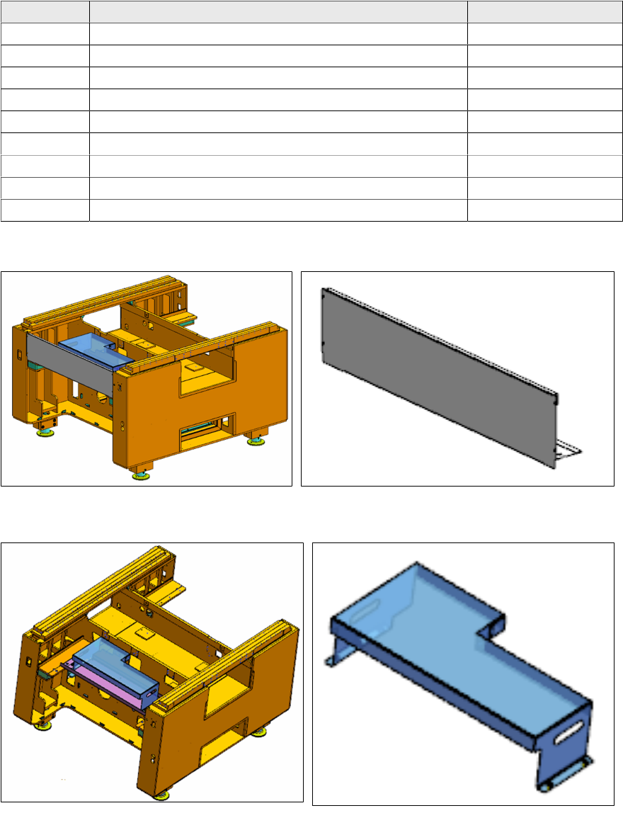
2.1 Preparing Steps
► Remove the front cover [03109665-xx] from location 2.
► Remove the tray setup plate location 2 [03111629-xx] from location 2 (this is an option, it may
not be present).
2 Installation of Location 2 Upgrade Kit
2.1 Preparing Steps
Assembly Instructions E by SIPLACE
Location 2 Upgrade Kit 04/2017
14
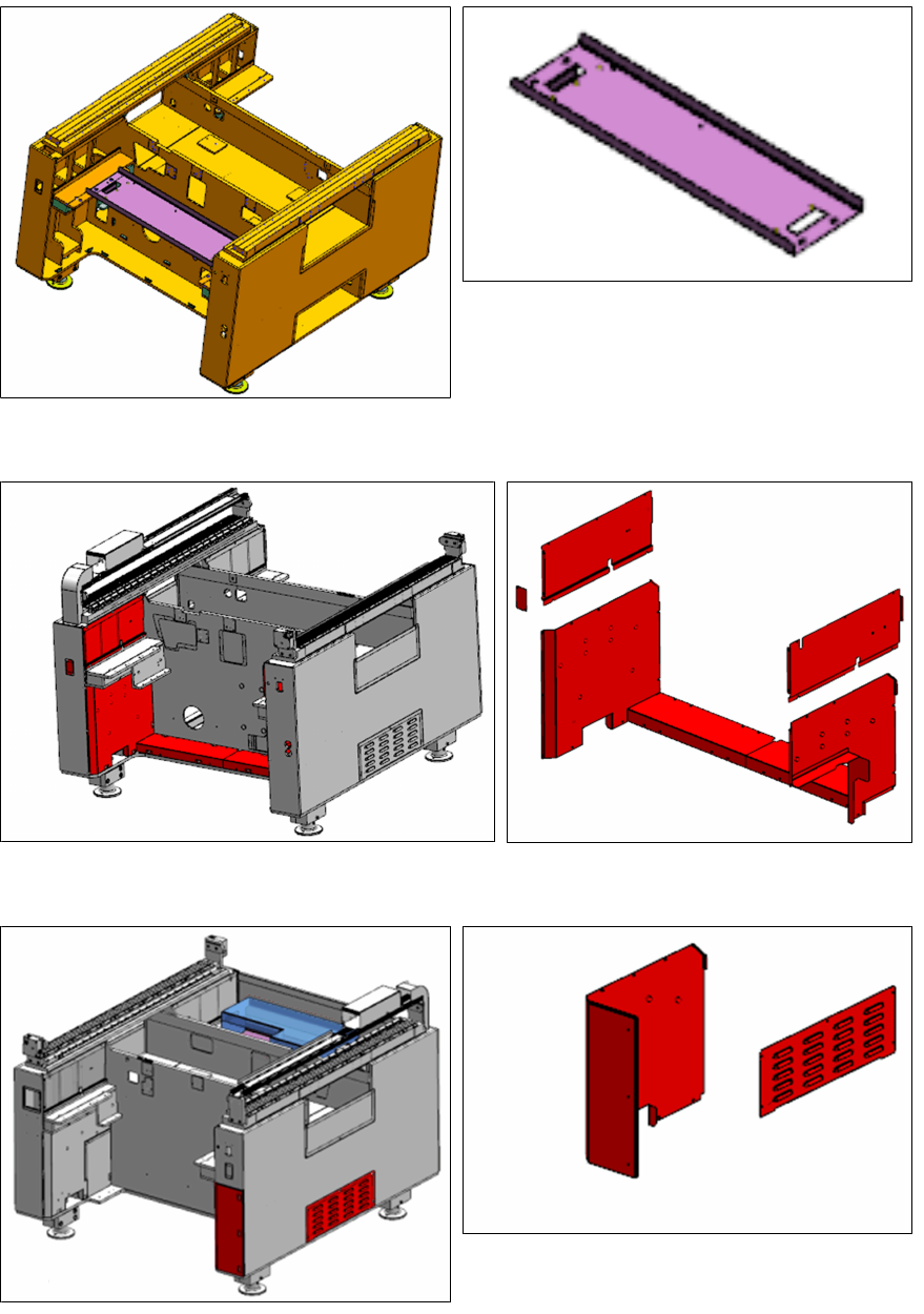
► Remove the Location 2 safety plate [03110130-xx].
► Remove the seven covers from location 2 as shown.
► Remove the side cover and cover from location 1 as shown.