00198351-01_AI_Location 2 Upgrade Kit_E by SIPLACE_en.pdf - 第17页
Assembly Instructions E by SIPLACE Location 2 Upgrade Kit 04/2017 2 Installation of Location 2 Upgrade Kit 2.2 Installing the Cable Branch Option, Location 2 HMI Extension 17 ► Install the E-series table insert right sub…
2 Installation of Location 2 Upgrade Kit
2.2 Installing the Cable Branch Option, Location 2 HMI Extension
andE‑SeriesHMITowerKit
Assembly Instructions E by SIPLACE
Location 2 Upgrade Kit 04/2017
16
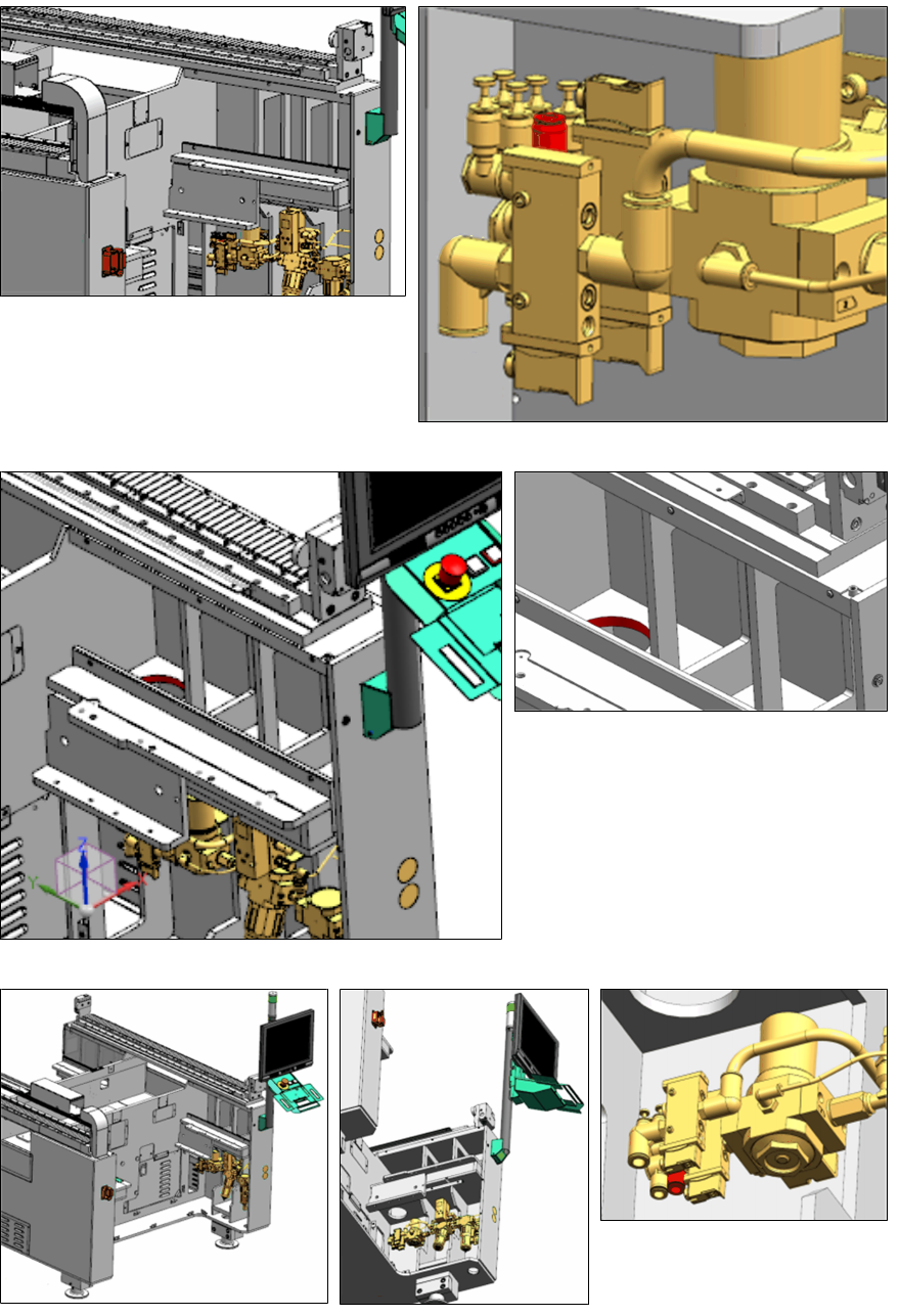
► Connect the tube INPUT-PSU_P6
[03111726-xx] to the highlighted port of
the Air Service Unit (port6).
► Route the tubing up through the in-
dicated hole and leave it there.
► Connect the tube "Tube Tape Cutter Location 2" [03102148-xx] to the highlighted port of the
Air Service Unit (portT2).
Assembly Instructions E by SIPLACE
Location 2 Upgrade Kit 04/2017
2 Installation of Location 2 Upgrade Kit
2.2 Installing the Cable Branch Option, Location 2 HMI Extension
17
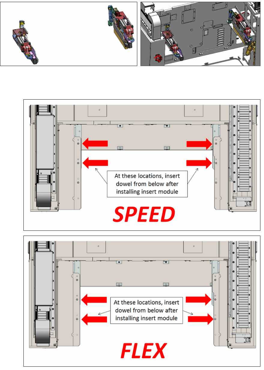
► Install the E-series table insert right sub-assembly [03104512-xx] and the E-series table insert
left sub-assembly [03104649-xx] onto the machine frame. Depending on your machine type
use the indicated dowel holes as shown below.
Speed:
Twin /
Flex:
2 Installation of Location 2 Upgrade Kit
2.3 Recommended Installation Steps
Assembly Instructions E by SIPLACE
Location 2 Upgrade Kit 04/2017
18
2.3 Recommended Installation Steps
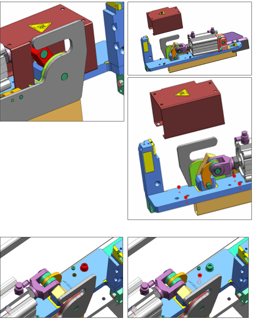
► Remove the safety cover to get access to
knock in dowel.
► Push the red part to a middle position to be
able to access all the four cover-mounting-
screws.
► The cover-mounting-screws that secure
the cover just need to be loosened, not re-
moved, as the cover is key-holed.
► Place the Insert Module on the frame at the correct location.
► Lightly secure with washer and M8x30 screw.
► Knock in the 8x28 dowel from the top, pay attention to the recommended orientation.