00198351-01_AI_Location 2 Upgrade Kit_E by SIPLACE_en.pdf - 第14页
2 Installation of Location 2 Upgrade Kit 2.1 Preparing Steps Assembly Instructions E by SIPLACE Location 2 Upgrade Kit 04/2017 14 ► Remove the Location 2 safety plate [03110130-xx]. ► Remove the seven covers from locatio…
Assembly Instructions E by SIPLACE
Location 2 Upgrade Kit 04/2017
2 Installation of Location 2 Upgrade Kit
2.1 Preparing Steps
13
2 Installation of Location 2 Upgrade Kit
In this chapter you will find the instructions for installation of Location 2 Upgrade Kit (i.e. from
Single side machine to double side machine).
Location 2 upgrade kit (for E-series) [03111361-xx] consists of the following:
Quantity Product name Item number
1 E-Series HMI Tower Kit 03109055-xx
1 E-series movable table system 03108761-xx
1 Location 2 Movable Table Covers 03112977-xx
1 Cable harness, COTi60 Location2 03106793-xx
1 Cable branch, option, LOCATION2 HMI extension 03107735-xx
4 ISO 4762 - M 4 x 12-A2-70 03042553-xx
8 Cable tie w=3.6mm l=140mm TY 24M 00805141-xx
1 E-Series HMI Tower Kit 03109055-xx
1 E-series movable table system 03108761-xx
2.1 Preparing Steps
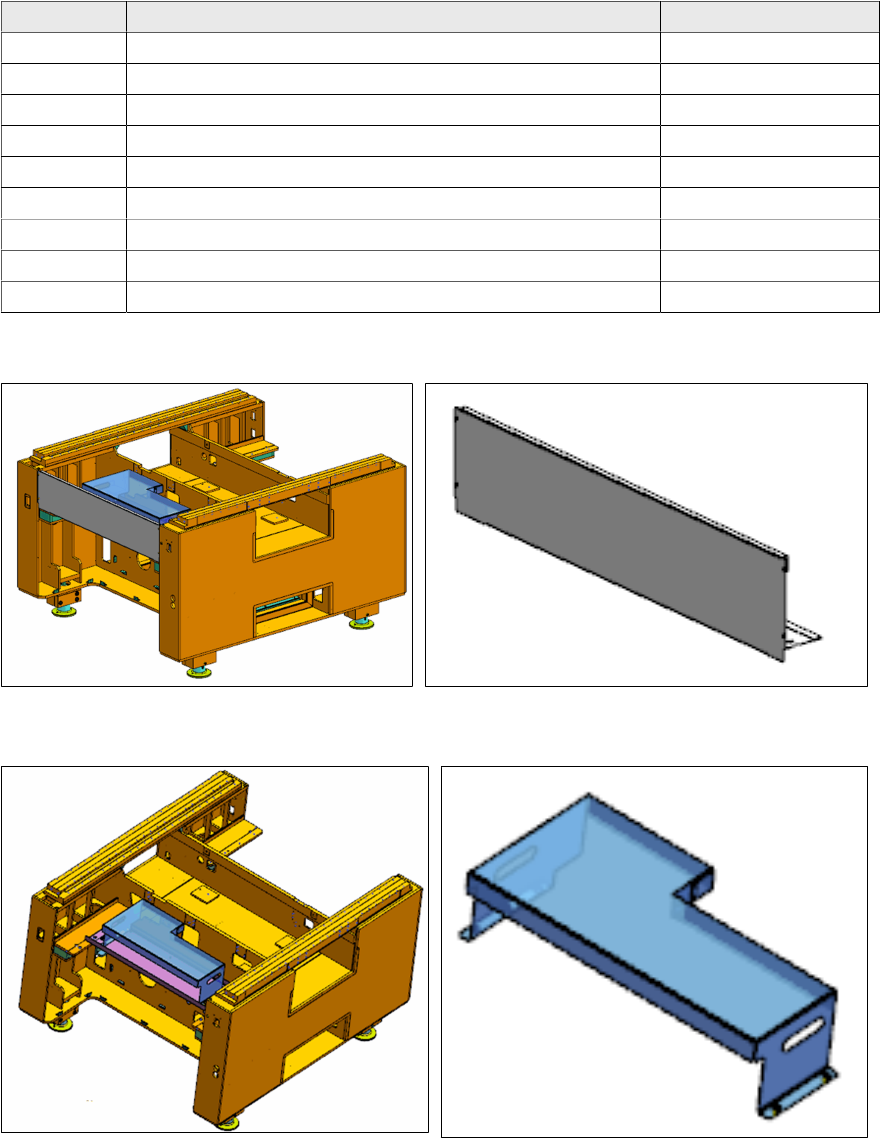
► Remove the front cover [03109665-xx] from location 2.
► Remove the tray setup plate location 2 [03111629-xx] from location 2 (this is an option, it may
not be present).
2 Installation of Location 2 Upgrade Kit
2.1 Preparing Steps
Assembly Instructions E by SIPLACE
Location 2 Upgrade Kit 04/2017
14
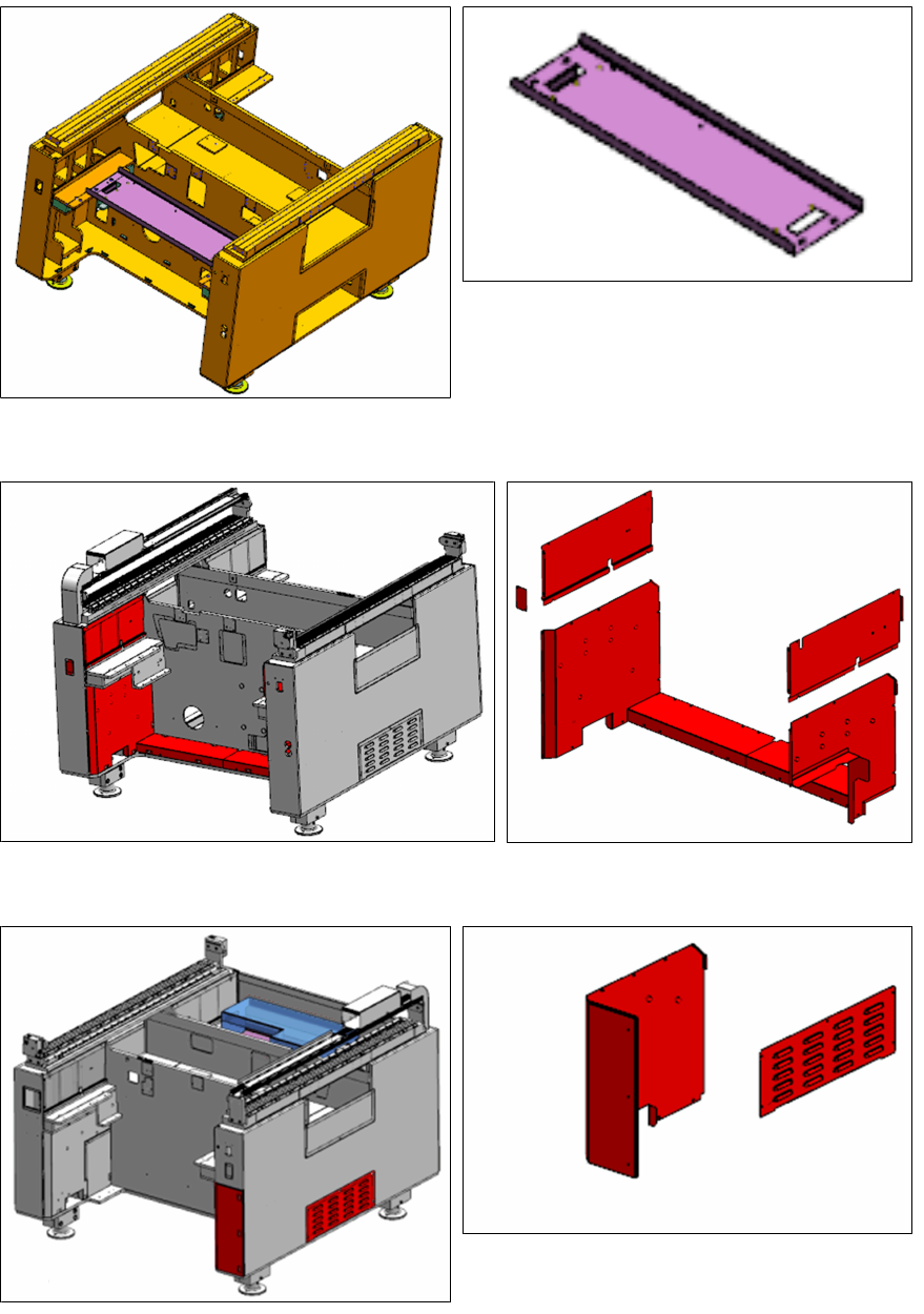
► Remove the Location 2 safety plate [03110130-xx].
► Remove the seven covers from location 2 as shown.
► Remove the side cover and cover from location 1 as shown.
Assembly Instructions E by SIPLACE
Location 2 Upgrade Kit 04/2017
2 Installation of Location 2 Upgrade Kit
2.2 Installing the Cable Branch Option, Location 2 HMI Extension
andE‑SeriesHMITowerKit
15
2.2 Installing the Cable Branch Option, Location 2 HMI
Extension andE‑SeriesHMITowerKit
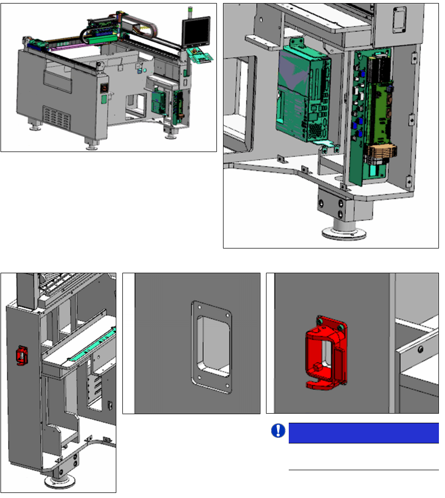
► Install the Cable branch option, location 2 HMI extension [03107735-xx] and E-Series HMI
Tower Kit [03109055‑xx] as per assembly instruction "2
nd
HMI and tower light for E-
series" [00197962‑xx].
► Connect the Cable [03105944-xx], control:
tape cutter 2 to the IOCU and route the
cable to location 2 of the machine.
NOTICE!
Pay attention to the orientation
of the release handle.
.
► Install the cable assembly base interface COT [03104481-xx] at the indicated area of
location 2.
► Connect the cable to the connections found in the compartment behind the cable housing.