N5194A矢量适配器数据表.pdf - 第17页
Page 17 Find us at www .keysight.com Fig ure 9. M eas ure d abs olute p has e nois e usi ng the ex ter nal LO m ode for N 51 92 A . Fig ure 10. Mea sur ed re sid ual p hase n ois e usin g the ex tern al LO mo de for N 5 …
Page 16
Find us at www.keysight.com
Figure 8. Measured AM noise using the external LO mode for the N5194A.
Measured external LO AM noise for N5194A
Phase Noise for N5192A
Absolute SSB phase noise (dBc/Hz), nominal
1
Offset from carrier
Frequency 20 kHz, nom
100 MHz –150
1 GHz –150
3 GHz –126
6 GHz –125
10 GHz –122
20 GHz –120
1. CW signal measured with power set to +5 dBm.
Page 17
Find us at www.keysight.com
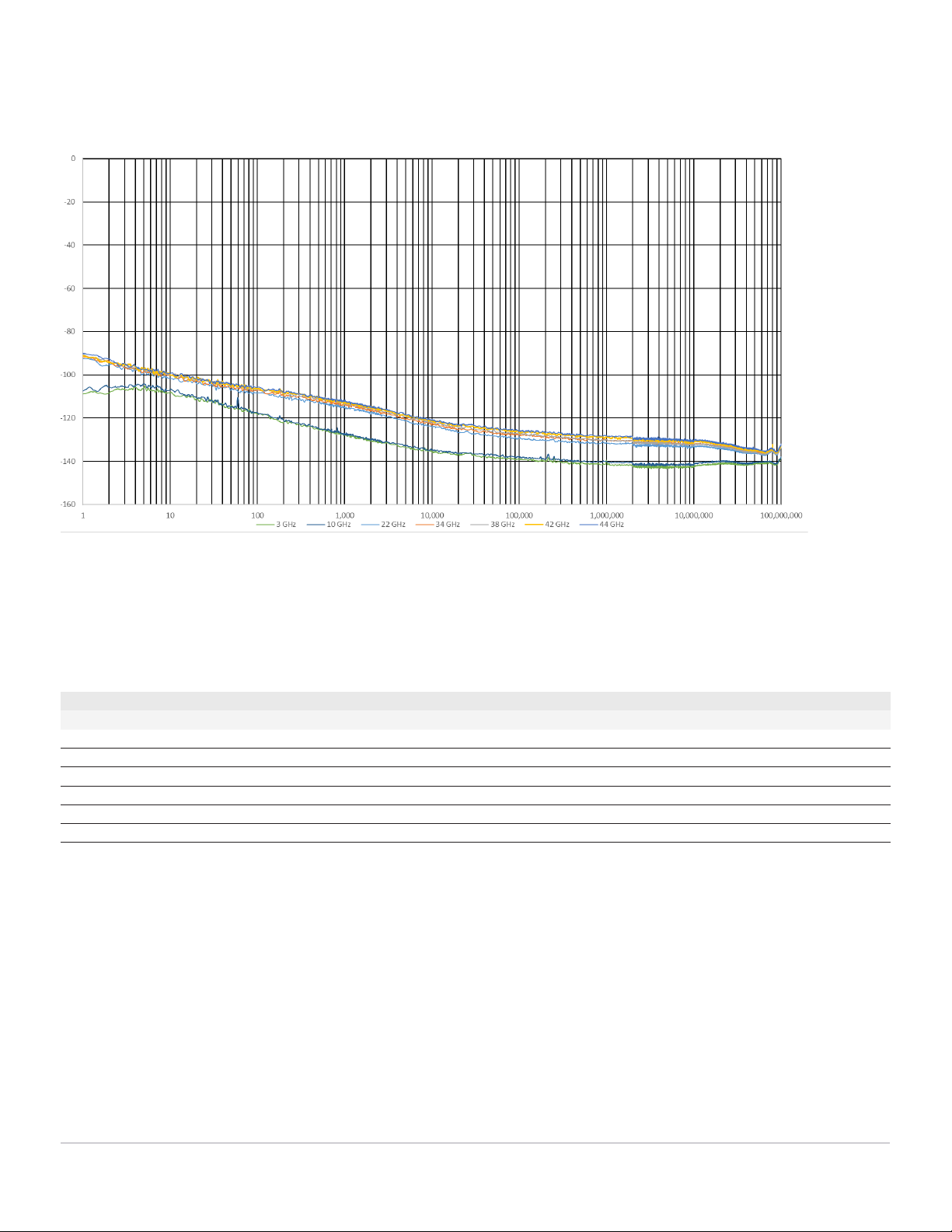
Figure 9. Measured absolute phase noise using the external LO mode for N5192A.
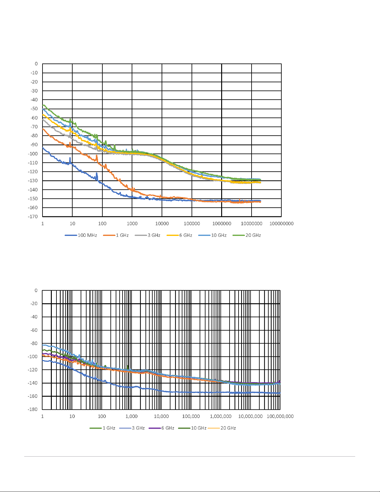
Figure 10. Measured residual phase noise using the external LO mode for N5192A.
Measured external LO absolute phase noise for N5192A
Measured external LO residual phase noise for N5192A
Page 18
Find us at www.keysight.com
Pulse Modulation
Pulse types
Defined by waveform
Pulse Waveform Maker – a built-in feature to define simple IQ pulse types. These can be called by the PDW. However, it does not have
marker capability.
On/Off ratio
Integrated over 100 Hz bandwidth
External LO mode 100 dB
Internal LO mode 105 dB
Rise/fall times
1
Defined by IQ waveform. Minimum rise/fall time
Vector mode 4.0 ns (nom)
Enhanced vector mode (opt BB2) 2.0 ns (nom)
Wideband vector mode (opt BB1) 0.5 ns (nom)
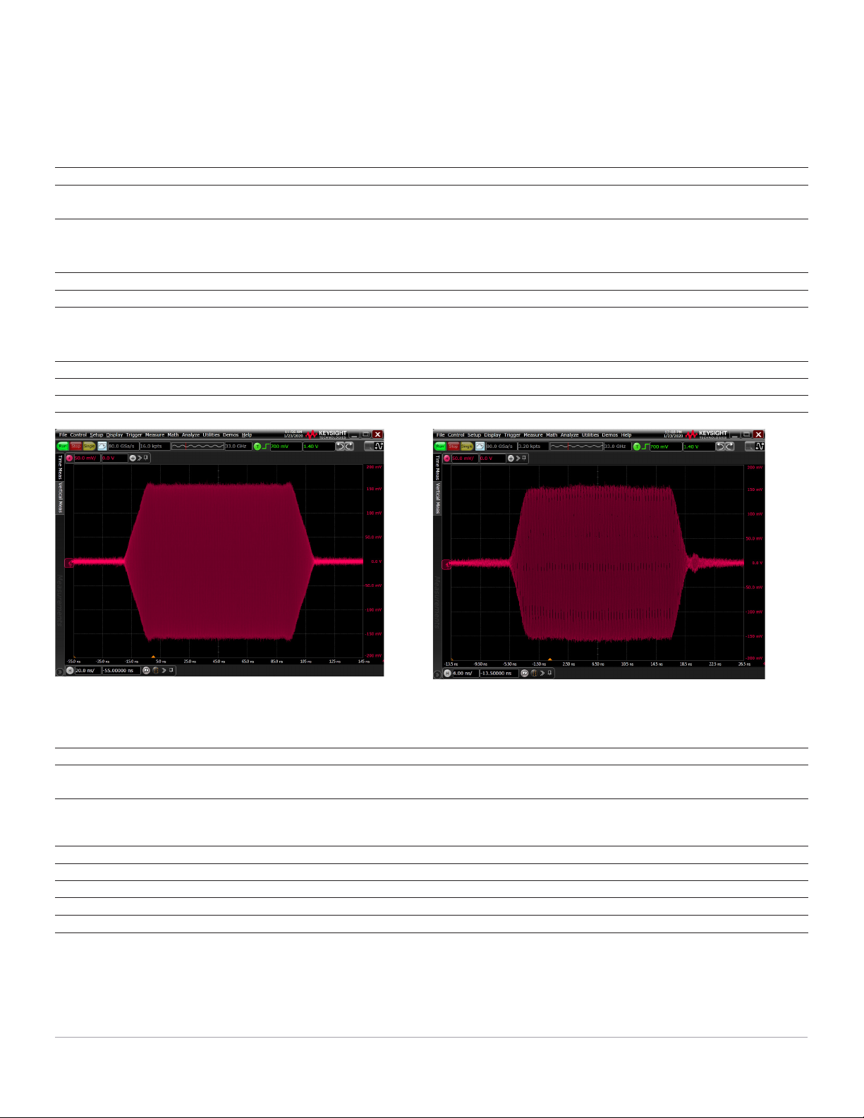
Figure 11. 100 ns pulse with 16 ns rise/fall times. Figure 12. 20 ns pulse with 2 ns rise/fall times.
Overshoot
Vector mode 4 % (typ) up to 32 GHz
Enhanced vector mode (opt BB2) or
Wideband vector mode (opt BB1)
10 % (typ) up to 32 GHz
3
Pulse Width
2
Minimum Maximum
Vector mode 8 ns (nom) 8 ns (nom)
Enhanced vector mode 2 s (nom) 4 ns (nom)
Wideband vector mode 2 s (nom) 1 ns (nom)
Pulse repetition interval 250 ns (nom)
1. Rise/fall times are determined by the sample rate, but may experience degradation of pulse shape with extremely short rise/fall times. A minimum of 4 or more
samples is recommended for better rise/fall shape quality.
2. Pulse width is specified as the width of the RF ON pulse measured from the 50% points on the rising and falling edges. Minimum pulse width is determined
by the sample rate, but may experience degradation of pulse shape with extremely short rise/fall times. A minimum of 8 or more samples is recommended for
better pulse shape quality. Maximum pulse width is determined by the available baseband generator memory and sample rate.
3. Except at 2.199 GHz, where overshoot is 12% (nom).