N5194A矢量适配器数据表.pdf - 第6页
Page 6 Find us at www .keysight.com Additional contr i but ors to switching speed With L A N or USB co ntrol Add 9 00 µs (nom) fro m recei pt of SCPI comma nd RF phase set tli ng criteri a Final frequency 1 0 MHz to <…
Page 5
Find us at www.keysight.com
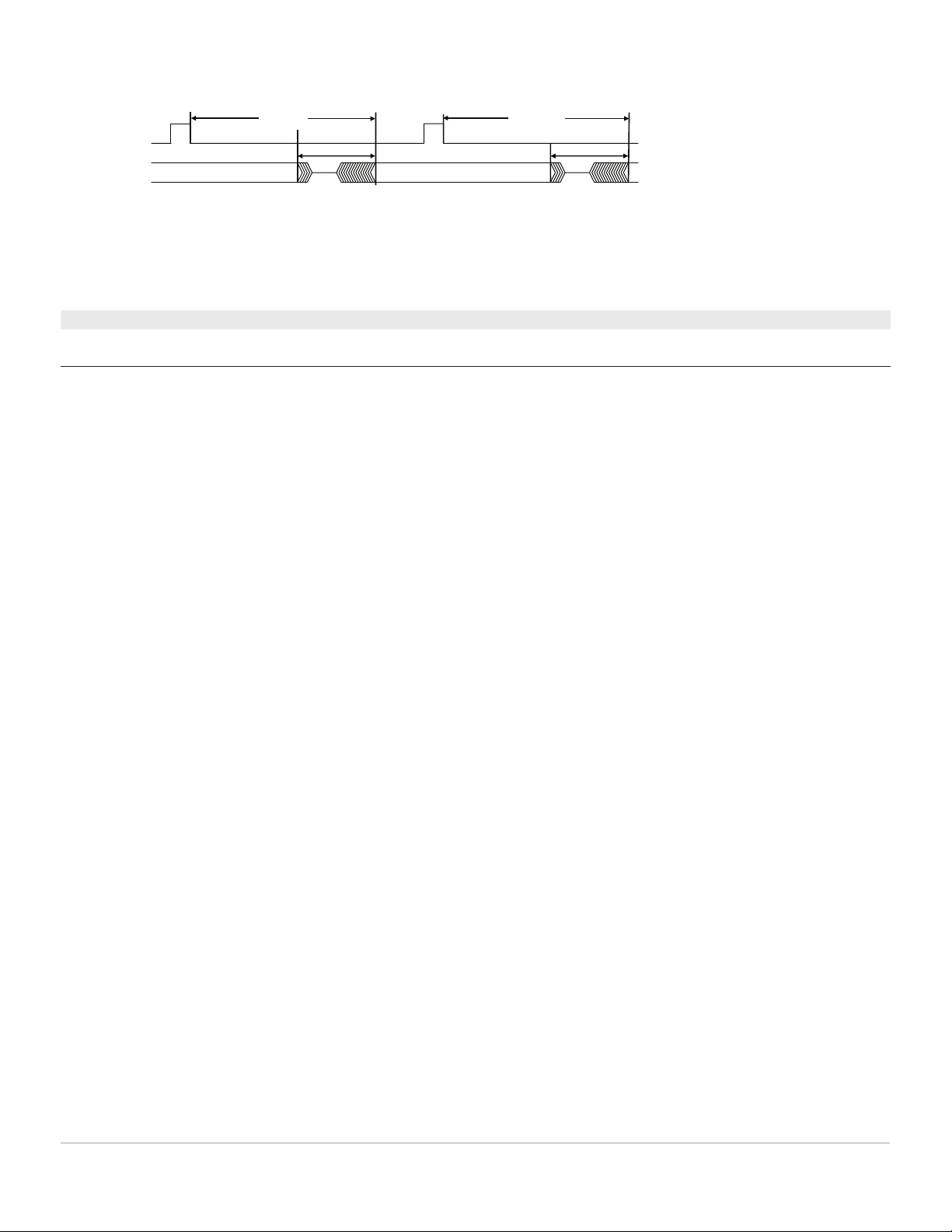
CW RF output
Output undefined
Input trigger
Latency
Transition time
Output undefined
Latency
Transition time
Figure 1. Switching speed definitions with input trigger
Switching speed for N5192A
1, 2
External LO mode, narrowband, nom External LO mode, wideband, nom
Update rate (transition time between
pulses in streaming)
101 µs 101 µs
1. For streaming mode only. Update rate refers to the transition time from the finishing of the leading pulse to the phase and amplitude settled in the following
pulse. The diagram in N5194A section doesn’t apply.
2. The N5192A does not have specified phase repeatability.
Page 6
Find us at www.keysight.com
Additional contributors to switching speed
With LAN or USB control Add 900 µs (nom) from receipt of SCPI command
RF phase settling criteria
Final frequency
10 MHz to < 2.85 GHz Measured to phase settled within 0.1 radians of final phase
2.85 GHz to < 8.64 GHz Measured to phase settled within 0.2 radians of final phase
8.64 GHz to < 17.3 GHz Measured to phase settled within 0.3 radians of final phase
≥ 17.3 GHz Measured to phase settled within 0.4 radians of final phase
RF amplitude settling criteria
50 MHz to 40 GHz Measured to amplitude settled to within 1 dB of final amplitude
Amplitude
Maximum CW power
1, 2
Option 520 or 52E Max available power Max specified power
Frequency External LO mode,
dBm spec (typ)
Internal LO mode,
dBm spec (typ)
External LO mode,
dBm spec
Internal LO mode,
dBm spec
10 MHz to < 2.5 GHz +6 (+7) +6 (+7) +3 +3
2.5 GHz to 4 GHz +7 (+8) +6 (+9) +3 +3
> 4 GHz to 14 GHz +7 (+10 ) +4 (+7) +3 +3
> 14 GHz to 18 GHz +6 (+8) +6 (+8) +3 +3
> 18 GHz to 20 GHz +1 (+4) –1 (+3) +1 –2
Option 540 Max available power Max specified power
Frequency External LO mode,
dBm spec (typ)
Internal LO mode,
dBm spec (typ)
External LO mode,
dBm spec
Internal LO mode,
dBm spec
10 MHz to < 2.5 GHz +5 (+7) +5 (+7) +3 +3
2.5 GHz to 4 GHz +5 (+8) +5 (+7) +3 +3
> 4 GHz to 14 GHz +5 (+7) +4 (+6) +3 +3
> 14 GHz to 18 GHz 0 (+3) 0 (+3) 0 0
> 18 GHz to 20 GHz –4 (0) –4 (0) –4 –4
> 20 GHz to 35 GHz –2 (+1) N/A –2 N/A
> 35 GHz to 40 GHz –5 (–1) N/A –5 N/A
1. Maximum CW power specifications are warranted from 15 to 40 ˚C. Maximum power in the 40 to 50 ˚C temperature range typically degrades less than 1 dB.
2. Instrument specifications are based on max specified power, unless otherwise stated. When operating at max available power, spectral purity will be
degraded.
Page 7
Find us at www.keysight.com
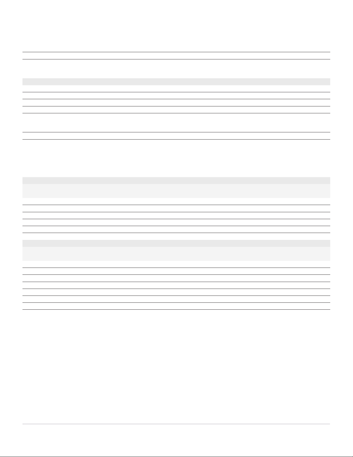
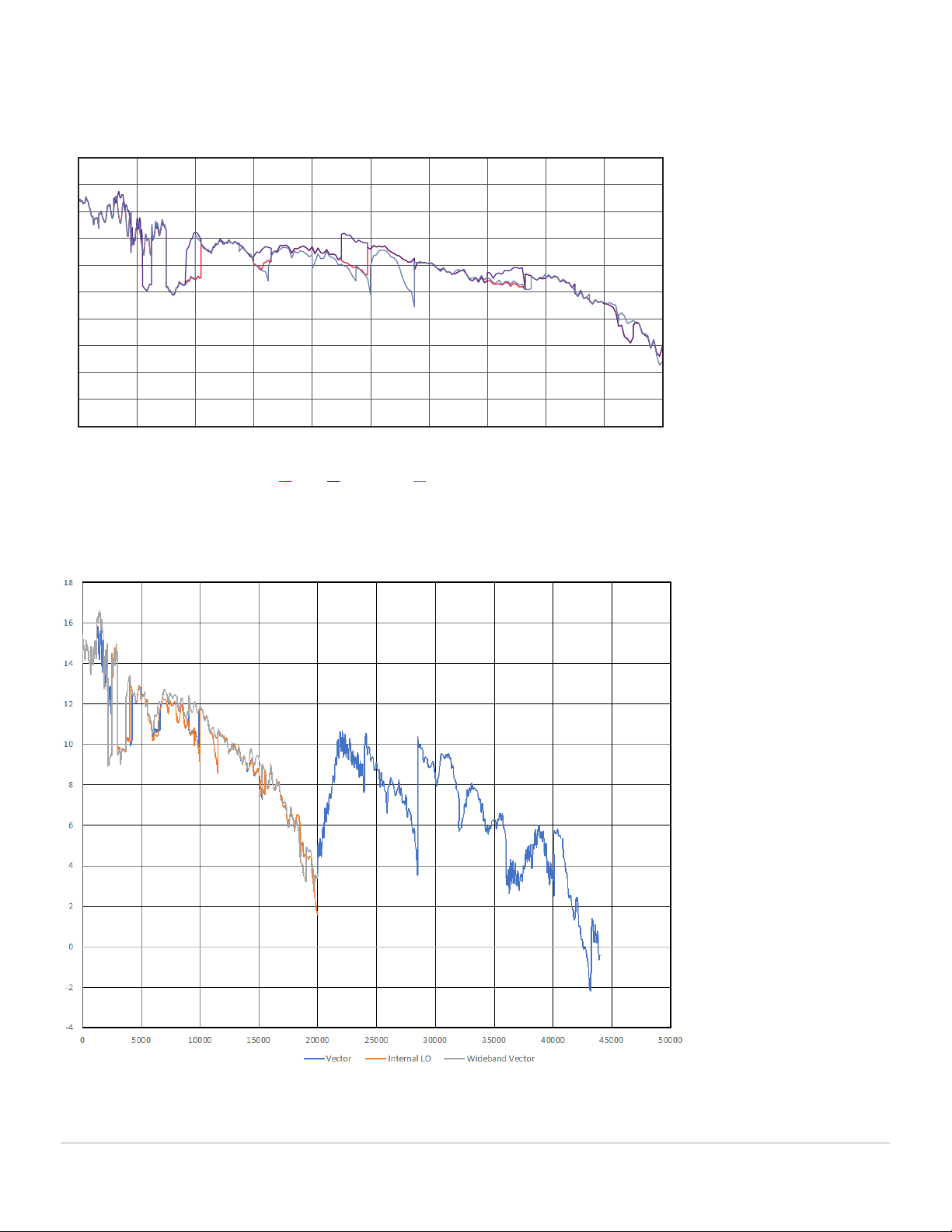
Figure 2: Maximum CW power (measured).
Maximum power, Option 520 or 52E
Vector Wideband vector Internal LO
Frequency (MHz)
0
2
4
6
8
10
12
14
16
18
20
0 2000 4000 6000 8000 10000 12000 14000 16000 18000 20000
Maximum power, Option 520 or 52E
Maximum power, Option 540