N5194A矢量适配器数据表.pdf - 第7页
Page 7 Find us at www .keysight.com Fig ure 2 : Ma ximu m CW power (m eas ure d). Ma ximum po wer, Option 520 or 52 E Vect or Wideband vector Internal LO Frequency (MHz ) 0 2 4 6 8 10 12 14 16 18 20 0 2000 4000 6000 8000…

Page 6
Find us at www.keysight.com
Additional contributors to switching speed
With LAN or USB control Add 900 µs (nom) from receipt of SCPI command
RF phase settling criteria
Final frequency
10 MHz to < 2.85 GHz Measured to phase settled within 0.1 radians of final phase
2.85 GHz to < 8.64 GHz Measured to phase settled within 0.2 radians of final phase
8.64 GHz to < 17.3 GHz Measured to phase settled within 0.3 radians of final phase
≥ 17.3 GHz Measured to phase settled within 0.4 radians of final phase
RF amplitude settling criteria
50 MHz to 40 GHz Measured to amplitude settled to within 1 dB of final amplitude
Amplitude
Maximum CW power
1, 2
Option 520 or 52E Max available power Max specified power
Frequency External LO mode,
dBm spec (typ)
Internal LO mode,
dBm spec (typ)
External LO mode,
dBm spec
Internal LO mode,
dBm spec
10 MHz to < 2.5 GHz +6 (+7) +6 (+7) +3 +3
2.5 GHz to 4 GHz +7 (+8) +6 (+9) +3 +3
> 4 GHz to 14 GHz +7 (+10 ) +4 (+7) +3 +3
> 14 GHz to 18 GHz +6 (+8) +6 (+8) +3 +3
> 18 GHz to 20 GHz +1 (+4) –1 (+3) +1 –2
Option 540 Max available power Max specified power
Frequency External LO mode,
dBm spec (typ)
Internal LO mode,
dBm spec (typ)
External LO mode,
dBm spec
Internal LO mode,
dBm spec
10 MHz to < 2.5 GHz +5 (+7) +5 (+7) +3 +3
2.5 GHz to 4 GHz +5 (+8) +5 (+7) +3 +3
> 4 GHz to 14 GHz +5 (+7) +4 (+6) +3 +3
> 14 GHz to 18 GHz 0 (+3) 0 (+3) 0 0
> 18 GHz to 20 GHz –4 (0) –4 (0) –4 –4
> 20 GHz to 35 GHz –2 (+1) N/A –2 N/A
> 35 GHz to 40 GHz –5 (–1) N/A –5 N/A
1. Maximum CW power specifications are warranted from 15 to 40 ˚C. Maximum power in the 40 to 50 ˚C temperature range typically degrades less than 1 dB.
2. Instrument specifications are based on max specified power, unless otherwise stated. When operating at max available power, spectral purity will be
degraded.
Page 7
Find us at www.keysight.com
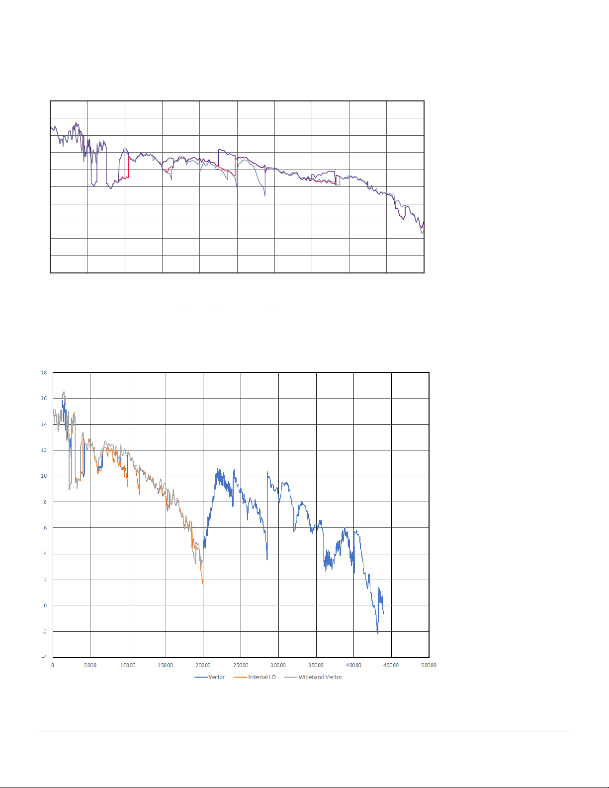
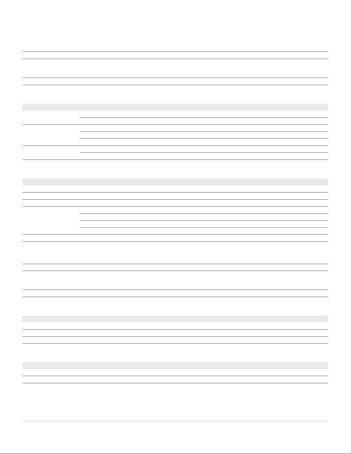
Figure 2: Maximum CW power (measured).
Maximum power, Option 520 or 52E
Vector Wideband vector Internal LO
Frequency (MHz)
0
2
4
6
8
10
12
14
16
18
20
0 2000 4000 6000 8000 10000 12000 14000 16000 18000 20000
Maximum power, Option 520 or 52E
Maximum power, Option 540
Page 8
Find us at www.keysight.com
1. CW power accuracy specifications are warranted from 0 to 50 ˚C. Specifications apply within ± 3 ˚C of last power alignment. Temperature compensation is
ON. If temp comp is OFF, amplitude drift will be ≤ 0.2 dB/˚C. For instruments with Option 1ED Type–N connectors, specifications apply below 18 GHz and
performance is typically degraded 0.2 dB above 18 GHz.
2. Specifications apply in vector mode only, over a power range of –5 to –85 dBm.
Minimum settable CW power
–120 dBm
Attenuator range
0 to 65 dB in 5 dB steps
Agile power linearity
Frequency Output power, dBm External LO mode, dB spec (typ) Internal LO mode, dB spec (typ)
50 MHz to 14 GHz Max specified power to –90 dBm ± 1.00 (± 0.33) ± 1.00 (± 0.34)
0 to –120 dBm ± 1.65 (± 0.41) ± 1.65 (± 0.45)
> 14 GHz to 20 GHz Max specified power to –10 dBm ± 0.80 (± 0.20) ± 0.65 (± 0.2)
–10 to –90 dBm ± 1.05 (± 0.33) ± 1.00 (± 0.27)
–10 to –120 dBm ± 1.75 (± 0.50) ± 1.85 (± 0.47)
> 20 GHz to 40 GHz Max specified power to –50 dBm ± 1.00 (± 0.50) N/A
–50 to –80 dBm ± 1.20 (± 0.60) N/A
CW power accuracy
1
Frequency Output power, dBm External LO, dB spec (typ) Internal LO, dB spec (typ)
50 MHz to 18 GHz +3 to –25 ± 2.5 (± 0.4) ± 2.5 (± 0.4)
200 MHz to 18 GHz < –25 to –75 ± 2.5 (± 0.4) ± 2.5 (± 0.4)
700 MHz to 18 GHz < –75 to –90 ± 2.5 (± 0.5) ± 2.5 (± 0.5)
> 18 GHz to 20 GHz +1 to –25 ± 2.5 (± 0.5) N/A
–2 to –25 N/A ± 3.0 (± 0.5)
< –25 to –75 ± 2.5 (± 0.5) ± 2.5 (± 0.5)
< –75 to –90 ± 2.5 (± 0.5) ± 3.0 (± 0.6)
> 20 GHz to 40 GHz Max specified power to –50 dBm ± 2.5 (+0.5) N/A
Resolution
0.01 dB
Maximum reverse power
½ Watt, 0 VDC
VSWR (nom)
Frequency 0 dB atten ≥ 5 dB atten
50 MHz to 18 GHz 1.6:1 1.6:1
> 18 GHz to 20 GHz 1.9:1 1.6:1
> 20 GHz to 40 GHz 2.0:1 2.0:1
Phase linearity vs. power
2
Frequency
50 MHz to 16 GHz 1.0 deg RMS (nom)
> 16 GHz to 40 GHz 2.0 deg RMS (nom)