User-Manual-NeoDen-IN6-Reflow-oven.pdf - 第16页
14 ♦ Regularly add high temperature l ubricating oil to transfer chain bearings.

12
♦The heat temperature wave is adjustable according to the PCB. You can adjust the transfer
chain rotation speed to adjust the temperature. Reduce the transfer chain rotation speed can
increase the product heat temperature. On the contrary, you can reduce the product heat
temperature.
Attention:
♦If the PCB has been placed components, the PCB pass the reflow and it reflow not very
completely, suggest you adjust then reflow again. Normally, it will not impact the PCB and
components.
♦From low to high when set temperature. If the heat range is over the reflow temperature too
high, should increase the transfer chain rotation speed or reduce the set temperature.
♦Different PCBs boards have different heat transmission rate and heat absorption capacity, so it
requires the reflow oven offers different heated time and quantity of heating. To double-side
PCB, multi-board and other PCBs with many bonding pads, they have a higher temperature
setting. To one-side PCB, paper board and less bonding pads’ PCB, they have a lower
temperature setting. And it also be affected by quantity of PCB that you place. During actual
work, reflow oven will adjust itself automatically to some changes of PCB. If based on our
suggested temperature, the machine can work well, unless very big change of PCB’s
absorption capacity, then it needs to adjust properly.
7. Temperature measurement method
♦Attach the temperature thermocouple sensor to the PCB which is the same or similar size as
the working PCB in order to observe the reflow. Put the PCB on the transfer chain, then will
get the temperature profile, after that compare with the recommend temperature profile. If it is
the same to the standard profile or correspond with automodulation profile, then you can start
to produce, otherwise follow the temperature profile, the temperature controller with large
temperature difference is used to set the compensation temperature by 5 degrees, or the whole
machine integrated adjustment, in order to achieve the temperature profile can be produced
♦When starting to put PCB or abruptly change the number of PCB to be reflow oven, there is a
difference between the actual temperature and setting temperature, put the PCB with constant
speed for a period of time, the temperature difference will turn to normal temperature
difference range.
8. Both side soldering instruction
♦Use hot air reflow soldering can finish double-side component soldering. Double-side
soldering design means components are in double-side of the PCB need to soldering. Double
side soldering includes double-side soldering tin and single-side soldering tin and another side
drying glue, as for single-side soldering tin and another side drying glue, it is easier. First,
finish one side’s soldering tin as the same as single-side, then finish another side tape glue
drying in low temperature, finish double-side SMT craft, after that carry on the next step plug-
in or tin process on craft. Double-side soldering is generally treated as below follows:
♦Start the reflow oven, set up the transfer chain speed controller, finish the A side components
reflow soldering with normal soldering craft.
♦Upend the PCB, repeat normal procedure to mount the component, adopt top heating strategy
to let the B side reflow soldering, but the upend A side has been reflow soldering, the
compounds in thick liquid volatilize, the melting point of tin is higher than the solder paste,
which in order to keep the A side components not fall out.
13
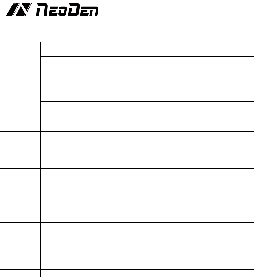
9. Trouble shooting
9.1 Soldering analysis
Problem
Possible causes
Solutions be available
Incomplete
reflow
Inadequate heating
lower the transfer chain speed
Shadows from components
a. Increase the transfer chain speed
b. Increase bottom heat
Due to the middle layer of copper foil
Decrease transfer chain speed and increase
temperature
Inadequate
moist
PCB, components without enough solder
paste
Pre-paste to components and PCB
No enough moist time
Increase the temperature of heating zone
PCB bend
Exceeding upper and lower temperature
difference limits
Reduce temperature difference between
preheating zone and bottom temperature zone
Increase transfer chain speed
PCB
discoloration
Exceeding tin temperature on the board,
exceeding temperature gradient or
heating speed
Increase transfer chain speed
Decrease the preset zone temperature
Decrease transfer speed and temperature
Excessive fines
Top layer temperature out of limit
Reduce top heat and increase bottom zone
temperature
Tin balls
Due to dry too fast
Decrease transfer chain speed and temperature
Solder pasting is unqualified or PCB re-
paste
Use PCB after cleaning and drying
Flux coking
Over heating
Add transfer chain speed, lower temperature
Components
wrong position
PNP wrongly, the tin on the solder pad is
irregular or asymmetrical, drying too fast
causes airflow to blow components
Check place position
Check the shape and thickness of tin
Lower transfer chain speed and temperature
Tin bridging
Misposition
Check position
Tin migration
Moist overtime
Increase the belt speed
Lower pre-setting temperature
Solder skips
The solder paste is not enough on pad,
the unevenness of the micro-component,
the PCB coplanarity problem
Thickened tin paste coating
Try to make the solder on the pad even
Check component pin stability
PCB over heat
Heating speed too fast
Decrease transfer chain speed and temperature
9.2 Precautions
If the PCB length is longer than the ESD tray, the ESD tray needs to be replaced by other
suitable carriers to place the soldered PCB.
9.3 Machine maintenance
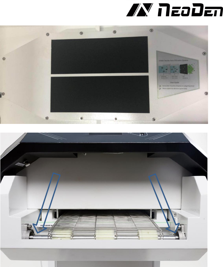
♦Change the filter regularly
It is necessary to replace the filter regularly. The service life of filter is 8 months (depending on
the frequency of use). When it’s needed to replace the filter, you could find the welding smoke
automatic filter system in the figure below. Remove the 12 screws above and replace the filter.
14
♦Regularly add high temperature lubricating oil to transfer chain bearings.