IPC CH-65B CHINESE.pdf - 第37页
18. Lee, .C., & Bixenman, M. (2001). Lead Free: How flux technology will differ for lead-free alloys. epcon W est. Anaheim, CA. 19. Triggelen-Aarden, I.V ., & W esterlaken, E. (2008). Performing flux technology…

要建立在部件的清洁度。
10
当施加电压的电路中存在着水分,离子残留围绕金属引线将开始电化学迁
移。
21
就算是在金属引线被腐蚀前,这种腐蚀现象已经影响它的导电性。
3.6.6 可靠性风险 可靠性问题的高风险可能会发生,尤其是在高可靠性的终端使用环境。在免洗
环境的设施内不好的工艺控制将增加风险,特别是在工艺控制调整可以实时被进行的情况下。免洗
工艺的实现将清洗和相关的工艺控制移转到多个出价最低的供货商
。最终测试和出货给客户之前,
潜在的可靠性问题有机会得到纠正。如果组件施加了敷形涂覆层,这一点尤其重要。
当处理免洗组件,设备和人力都需要执行测试和分析来确保输入元器件和电路板的清洁度。所有供
货商的制造工艺的资格核定以确保输入部件符合制造工艺标准。这个问题随着供货商和供货商制造
场所数量的增加而变得更加繁琐。
原始设备制造商要求供货商/用户/客户就现有的行业水平和测试
方法文件达成一致;或者产生任何目前不存在的文件。
参考⽂献
1. Fisher, J. (2008, Oct). IPC Technology Roadmap Future of Interconnection Technology and Its Impact on
Cleaning and Reliability. IPC/SMTA High Performance Cleaning Symposium.
2. Oosterhof, A., Ellis, B., Pauls, D., & aisbitt, G. (2008, Jan). What is involved with going no-clean?
Retrieved from http://listserv.ipc.org/scripts/wa.exe?A0=Techet
3. Lee, .C. (2008, Oct). Lead-Free Flux Technology and the Influence on Cleaning. IPC/SMTA High Per-
formance Electronic Assembly Cleaning Symposium.
4. Russeau, J. (2008, Oct). Utilizing and understanding the various methodologies for evaluating cleanliness
of printed wiring assemblies. IPC/SMTA High Performance Cleaning Symposium.
5. Bixenman, M., Ellis, D., & eiderman, J. (2009, April). Collaborative cleaning process innovations from
managing experience and learning curves. IPC Printed Circuits Expo, APEX.
6. Munson, T. (2008). Process residues and their impact on product reliability. Forsite Labs, Kokomo, I.
7. Hillman, D. (2008, Oct). A reduced cleaning of printed circuit boards: The science of leaving residues
alone. IPC/SMTA High Performance Cleaning Symposium.
8. Bixenman, M., (2008, April). Quantifying cleaning relevance when manufacturing lead-free printed circuit
board assemblies. SMTA Conference on Soldering and High Reliability. Toronto, Canada.
9. aisbitt, G. (2008, March). Cleanliness testing on the shop floor. Surface Mount Technology.
10. Cullen, D.P., & O’Brien, G. (2004). Implementation of immersion silver PCB surface finishes in compli-
ance with underwriters laboratories. IPC Printed Circuits Expo, San Diego, CA.
11. Lee, .C. (2008). Future lead-free solder alloys and fluxes: Meeting the challenges of miniaturization. IPC
Printed Circuits Expo. Las Vegas, V.
12. Takemoto, T., Latanision, R.M., Eagar, T.W., &Matsunawa, A. (1997). Electrochemical migration tests of
solder alloys in pure water. Corrosion Science. 38(8), 1415-1430.
13. Seatman, K., & ishimura, T. (2008). Properties that are important in lead-free solders. IPC Printed Cir-
cuits Expo. Las Vegas, V.
14. Munson, T. (1998, ov.). Eliminating metal migration failures. Printed Circuit Fabrication. 21(11), 32.
15. Rudra, B., Pecht, M.J., & Jennings, D. (1996). Electrochemical migration in multichip modules. Circuit
World. 22(1), 67.
16. Hawes, A. (2000). Causes and effects of corrosion in plastic IC packages. Electronic Engineering.
17. Toleno, B., & Maslyk, D (2008). Process and assembly methods for increased yield of package on package
devices. IPC Printed Circuits Expo. Las Vegas, V.
IPC-CH-65B-C 2011年7月
22
Copyright Association Connecting Electronics Industries
Provided by IHS under license with IPC
Not for Resale, 11/27/2015 19:13:55 MST
No reproduction or networking permitted without license from IHS
--`,`,,,,`,`,,,`,,,`,`,`,`,,,```-`-`,,`,,`,`,,`---

18. Lee, .C., & Bixenman, M. (2001). Lead Free: How flux technology will differ for lead-free alloys.
epcon West. Anaheim, CA.
19. Triggelen-Aarden, I.V., & Westerlaken, E. (2008). Performing flux technology for Pb-free S100C
solders. IPC Printed Circuits Expo. Las Vegas, V.
20. Partee, B. (2004, Feb). SIR Testing. EMPF. Retrieved from http://www.empfasis/feb04/sirtesting.htm.
21. Pauls, D., & Munson, T. (2000, Jan). Questions and answers 1. Circuits Assembly. 11(1), 72.
22. Schweigart, H., & Wack, H. (2001, April). Humidity and pollution effects on Pb-Free assemblies. Circuits
Assembly. 18(4), 34.
23. Zestron Corporation, (n.d.) ‘‘Cost per cleaned part’’ is a term that was pioneered by Zestron Corporation
with the introduction of non-surfactant, modern aqueous product technologies.
24. GfKORR Working Group (n.d.). Corrosion protection in electronics and micro-system technology. Ingol-
stadt, Germany.
25. Richie, B. (2008, Oct.). To Clean... or ot To Clean. IPC/SMTA High Performance Cleaning Symposium.
26. Keeping, J. (2008, Oct.). Critical considerations for selecting a conformal coating process. IPC/SMTA
High Performance Cleaning Symposium.
27. Schweigart, H. (2003). The reliability of silver-based solders. EPP Europe, 3⁄4 - 2003.
28. Schweigart, H., & Muehlbauer, A. (2002, Mar). Preventing contamination-caused assembly failure.
www.smtmag.com
29. Joint Services Solvent Substitution Working Group (JS3WG). http://www.jgpp.com/projects/JS3/
JS3_main.htm
30. James J. Andrus, Hollis Automation, Inc., ‘‘PWA Aqueous and Semi-Aqueous Cleaning: System
Approaches and Tradeoffs,’’ EPCO West Proceedings, pp 281-291, 1991 (also published as WC
TP-7110, pp 35-48, 1991)
4 组件清洗性设计
4.1 有效清洗组件的设计 由于微型化以及复杂的前沿产品,设计可清洗的印制电路组件已成为一
个非常具有挑战的任务。
1
电子产品可制造性设计(DFM)包括一套修改和提升印制电路和清洗工艺
设计的技术来配合清洗过程中的基板、污染物以及现有的清洗方法。使电子产品微型化、轻量化的
期望驱使设计者转向设计细间距的高密度组件。本章节目的是提供用于清洗前沿印制电路的设计准
则及方法。
随着技术的进步,使用更小的元器件、高密度布局、材料的变化,和环境条件重新提高了电路板清
洁度的重要性。
3
将印制电路组件设计得易于制造,需要计算机辅助设计(CAD)人员从了解制造工
艺及其局限性开始。作为一般规则,通孔组件比表面贴装组件产生的问题少,特别是那些在高密度
互连结构 (HDI)基板上的组件。问题是,在更小元器件的驱动下增加了元器件性能和功能的复杂
性。
2
这种复杂性使得有效去除残留物更加困难。
某些情况下,可能会在良好电气设计、良好焊接布局和良好清洗布局的要求之间有冲突。在这些情
况下,设计人员应该尝试找到适当的折衷方法。随着所有工艺的改变,清洗工艺相对于所提出的设
计必须经过评估。新的组件生产之前,所选择的清洗工艺必须经过验证。清洗工艺的评估应该涉及
设计人员、工程师、品管人员、车间人员、安全/环保顾问和其它关键人员。清洗工艺包括清洗剂、
清洗设
备和清洗方案。清洗工艺应该被演示人员接受;否则,新工艺是不太可能成功。
2011年7月 IPC-CH-65B-C
23
Copyright Association Connecting Electronics Industries
Provided by IHS under license with IPC
Not for Resale, 11/27/2015 19:13:55 MST
No reproduction or networking permitted without license from IHS
--`,`,,,,`,`,,,`,,,`,`,`,`,,,```-`-`,,`,,`,`,,`---
小组会议,包括关键人员往往有助于培养设计人员;这种方法可能是做可制造性设计的最快捷的方
法。当清洗高密度表面贴 装组件时,计算机辅助设计系统应该调整为确保每一步能够提高清洗能
力。这可能意味着元器件应该面向一个特定的方向,为实现这一目标,它可能需要一个或者多个额
外的信号层。如果因为经济原因而不可能采取这种方式时,那么可能
必须在电压层或者接地层插入
信号导体。在具有微导通孔的高密度互连结构情况下,通常是在焊盘中有导通孔。这排除了元器件
扇出(狗骨形)的需要,允许更高的元器件密度,如此可能严重危害清洗工艺技术的现状。
4.2 清洗设计 印制电路板按照既定的行业标准进行设计、组装和品质控制。为了减轻由于污染造
成产品失效的风险,清洗工艺必须提供一个已定义的工艺窗口,该窗口是可
重复的,并且是横跨组
装工艺中所遇到的变量的广阔区间。为实现一个高良率的清洗工艺,许多因素影响着清洗工艺窗
口:基板、污染物、可用的清洗技术、清洗设备和环境因素。
4.2.1 基板 设计清洗工艺的第一步是彻底审查印制线路板布局以确定镀覆孔、孔的厚径比、任何
适用堵塞或者掩蔽的导通孔和阻焊膜材料的选择。部件组成、尺寸和几何形状可以创造细间隙和小
出口的夹层元器件,而导致很难去除
残留物。当小型和轻量的部件通过清洗工艺时,会增加夹持组
件的需求。清洗工艺设计首先考虑电路板表面、金属化和兼容性的限制。部件独特的限制可能会使
一些元器件在进行清洗工艺时受到限制。
4.2.1.1 裸板清洗要求 经过电镀和化学蚀刻工艺后,离子污染物成为导电残留物余留在印制电路板
的表面上。导电离子来自于金属清洗剂、蚀刻剂、电镀化学品、热熔液和整平液、加工设备和人体
接触。用于热风整
平工艺的助焊剂可能夹裹在焊盘与阻焊膜之间的间隙或者掩蔽导通孔内。对于来
料裸板,考虑掩膜到金属的间距紧密区和掩蔽导通孔的设计对清洗能力影响不大。裸板通常有不可接
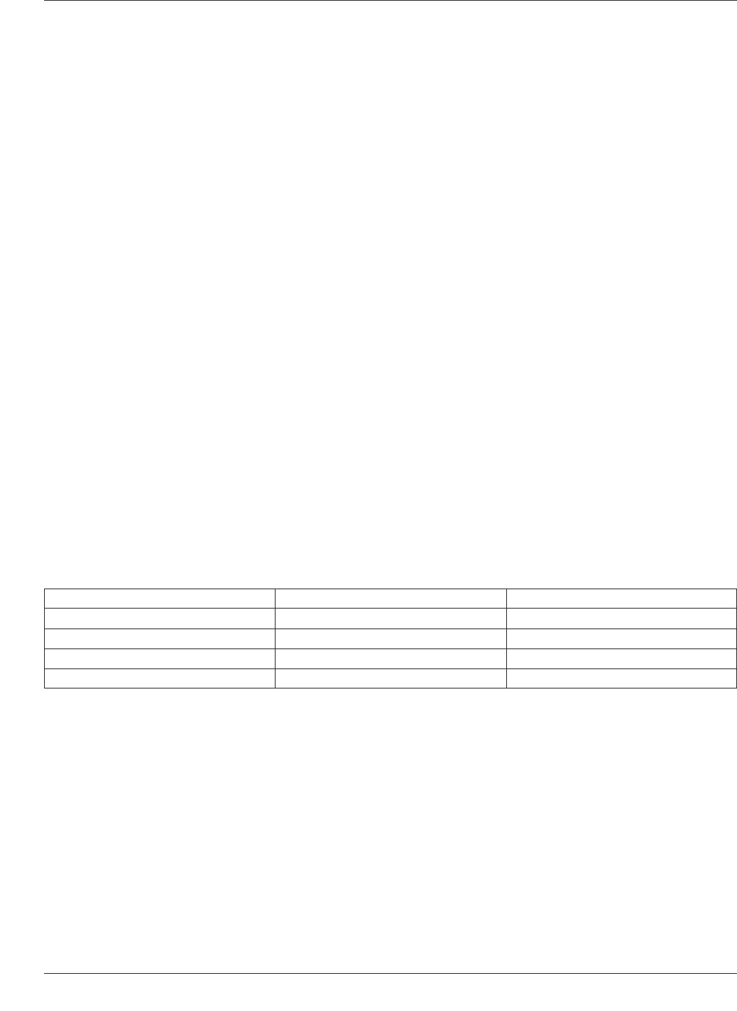
受的来自于制作工艺的加工残留物。IPC-5704规定:按照IPC-TM-650测试方法2.3.28.2进行测试,
接受态的单面或者双面和多层印制板应当符合表4-1中列出的各表面处理方法对应的离子清洁
度的要
求。不适当的组件设计和布局往往造成清洗困难。未完全固化的阻焊膜和/或者图例油墨也会对焊接
后和清洗的外观有不利影响。
4.2.2 组装元器件 元器件微型化促使电子产品更小和更轻,减少元器件之间的间距,增加了性能
和功能的复杂性。
2
高密集组件使用低特征(Z-高度)的元器件,占据了印制电路板上的重要区域。
这些元器件如封装体叠层、片式电容、QF、CSP等。而减少元器件的尺寸和间距增加了元器件端接
口及元器件下方这两处的清洗困难。
使用微型元器件会造成清洗的挑战增加,如电阻和电容器。01005电阻的尺寸非常小,尺寸为0.4x0.2
mm[0.016inx0.008in]。在焊接工艺中,助焊剂会因
表面张力而填充到元器件的下方。元器件从印制
电路板表面算起的托高高度小于0.001mm[0.00004in]。由这些小元器件所建构的产品来看,若为了
电路板的功能正常,必须去除元器件下方所有残留物。
6
高引脚数封装元器件也呈现出高难度清洗的挑战,特别是清洗球栅阵列(BGA)和芯片尺寸封装
(CSP)的下方。由于数百到上千的引脚数量,了解助焊剂的选择、热梯度、清洗材料,以及清洗材
料的机械传递(即喷嘴)是很必要的。
表 4-1 裸印制板离⼦污染最⼤限值(μg/cm
2
)
离⼦ ⾮OSP OSP
氯化物(Cl) 0.75 0.75
溴化物(Br) 1.0 1.0
钠(a)+ 钾(K) 2.0 4.0
无机离子总量 3.8 5.9
IPC-CH-65B-C 2011年7月
24
Copyright Association Connecting Electronics Industries
Provided by IHS under license with IPC
Not for Resale, 11/27/2015 19:13:55 MST
No reproduction or networking permitted without license from IHS
--`,`,,,,`,`,,,`,,,`,`,`,`,,,```-`-`,,`,,`,`,,`---