MUMA-Hardware-manual-20120717.pdf - 第7页
- 7 - 3. Install MUMA 20 0 3.1 Computer request CPU: Pentiu m or bett er host co mputer(Advise CPU: Pentiu m 4 or bet ter one) RAM-Memory : At least 256MB or more(Advise memory : 512MB) HD -Hardware: The free disk …
- 6 -
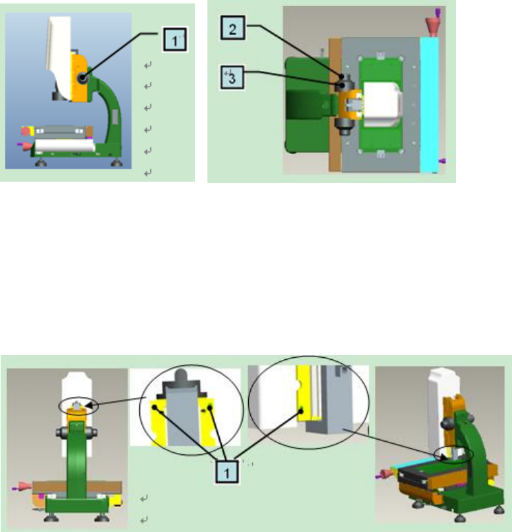
2.7 Roughly and Fine turning
1: Turn it to move Z axis up and down, divide into roughly and fine
2: Fine turning: move Z axis to reach a clear image which you expect
3: Roughly turning: move Z axis up and down quickly, handle slightly
2.8 Cover
1: 4 grub screws: fasten cover
Note: When remove cover, move Z axis up by roughly turning and loosen the two upper screws by
spanner, as the left picture. Then, move Z axis down and loosen the two lower screws by spanner, as
the right picture. All these done, remove the cover up slightly.
When replace the cover, aim at the cover groove and put it back slightly. Then tighten 4 grub screws.
Suggestion:If not necessary, please don’t remove the cover.
- 7 -
3. Install MUMA200
3.1 Computer request
CPU: Pentium or better host computer(Advise CPU: Pentium 4 or better one)
RAM-Memory: At least 256MB or more(Advise memory: 512MB)
HD-Hardware: The free disk space should be at least 50MB or more
Printer-Printer (Optional, use for printing the report data)
OS-Operating System :Windows 2000 or XP
Screen colors quality is for 32 bits, and the resolution has four kinds,1280×800,1366×768,
1440×900 and 1920×1080. Free-running card is 256M or more.
Input and output devices: At least 1 USB serial ports
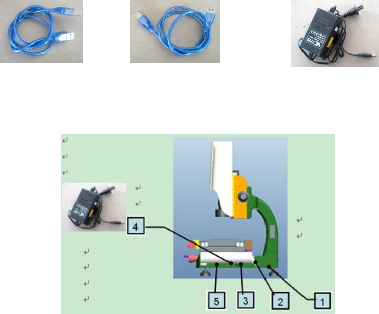
3.2 MUMA200 Cables
3.2.1 Cables
Machine USB signal cable: both sides are for USB type, but one is small and the other is large
(as pic1). Two sides of this cable are same (as pic2).
Machine external power cable: one side is circle, the other side is pin (as pic3).
Pic1 Pic2 Pic3
3.2.2 Connect with computer
Machine USB power cable, one side is connected with 4 signal interface on machine , the other
side is connected with computer.
Machine USB signal cable, one side is connected with three signal interface on machine, the
other side is connected with USB power cable, then connect the USB power cable with the computer.
- 8 -
Lockdog
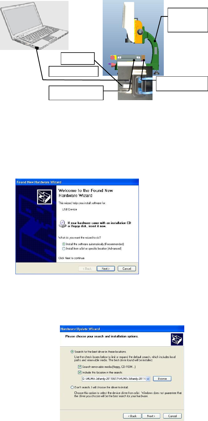
3.3 Driver Installation
Check all the cables connection, and then open computer and installation CD.
3.3.1 Camera installation
Start the computer.
A prompt, “Welcome to the Found New Hardware Wizard” will appear, choose “Install the
software automatically (Recommended)” and click “’next” to continue.
Choose “Include this location in the search”, click “Browse” to find “CCD-Driver”, and click “next”
to continue.
Camera driver installation is on progress.
USB power cable
External
power cable
Lockdog
USB signal cable
USB signal cable
External
power cable