00198171-02_Technical_Training_FSE_TX-Series_EN.pdf - 第36页
4 Gantry System 4.2 Reference Run 36 Technical Training FSE SIPLACE TX-Series 01/2018 Mechanical Structure of X Axis 1. Board (head interface with Vision board, below vertical – head adapter board) 2. Gantry arm made of …
4 Gantry System
4.1 Overview
Technical Training FSE SIPLACE TX-Series 01/2018 35
4 Gantry System
4.1 Overview
The gantries of the SIPLACE TX machines consist of one X and one Y Axis. Both axes are driven
by a linear motor which is equipped with an integrated temperature sensor. These temperature
sensors only monitor the motor coils. The placement heads are mounted on the head plates of the
respective XAxis.
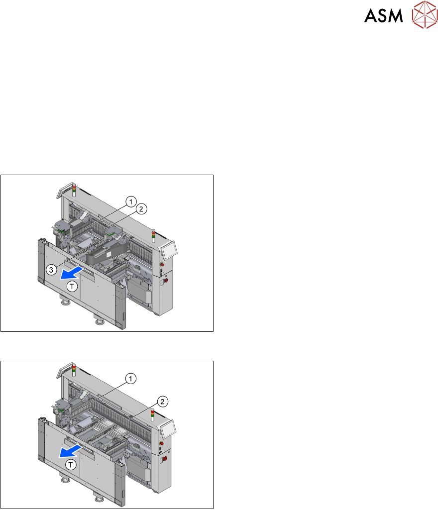
TX2i/TX2
T - Transport direction
1. X Axis, Gantry 1
2. Y Axis, Gantry 1 and Gantry 2
3. X Axis, Gantry 2
TX1
T - Transport direction
1. X Axis, Gantry 1
2. Y Axis, Gantry 1
4 Gantry System
4.2 Reference Run
36 Technical Training FSE SIPLACE TX-Series 01/2018
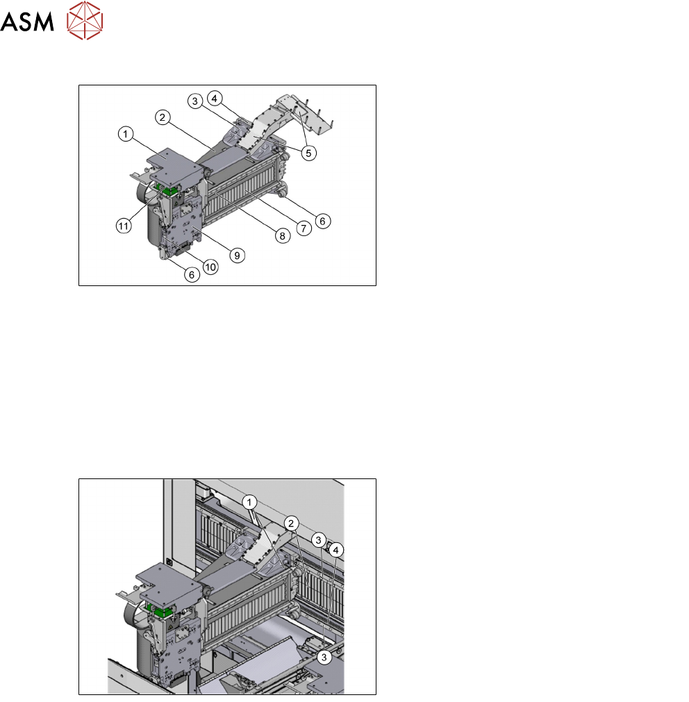
Mechanical Structure of X Axis
1. Board (head interface with Vision board,
below vertical – head adapter board)
2. Gantry arm made of carbon fiber
3. Sensor module for Y Axis*
4. YAxis linear motor (primary)
5. Trailing cable
6. XAxis end position bumper
7. Secondary parts XAxis (magnet)
8. Incremental scale / glass scale*
9. Head mounting plate with integrated
primary part of XAxis linear motor
10. Temperature sensor
11. Sensor module for X Axis (under the head
board)
*Only for TX micron
To improve placement accuracy, the temperature sensors are used to compensate machine cali-
bration data.
Mechanical Structure of Y Axis
1. Y linear motors (primary part) on the
XAxis gantry
2. Permanent magnet (secondary part of the
YAxis linear motor)
3. Linear guidance system
4. Incremental scale / glass scale*
* Only for TXmicron
4.2 Reference Run
After pressing start after machine boot up the axes move to a defined position. This is known as
the reference run.
4 Gantry System
4.2 Reference Run
Technical Training FSE SIPLACE TX-Series 01/2018 37
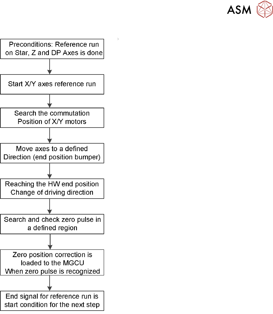
Reference Run Workflow
Reference Run detailed Workflow
Preconditions: Axis reference run must be successfully completed for the relevant placement
heads.
Commutation position search for 3 phases AC-drives on gantry during initial reference run:
1. Two motor phases are switched by the MGCU.
2. The 3-phase AC motor moves to the next suitable magnetic position.
3. Two other motor phases are switched by the power supply and the axis moves further.
4. These switching steps are repeated multiple times.
5. The axis reference run is continued with a reference position search for the position measur-
ing system.