00198171-02_Technical_Training_FSE_TX-Series_EN.pdf - 第43页
4 Gantry System 4.5 Control and Communication Overview Technical Training FSE SIPLACE TX-Series 01/2018 43
4 Gantry System
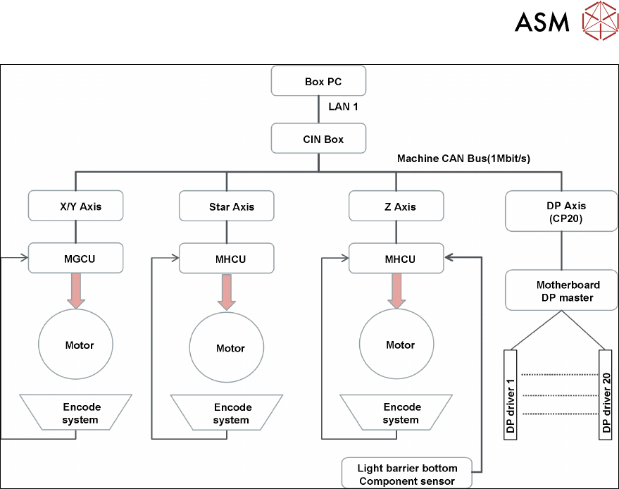
4.5 Control and Communication Overview
42 Technical Training FSE SIPLACE TX-Series 01/2018
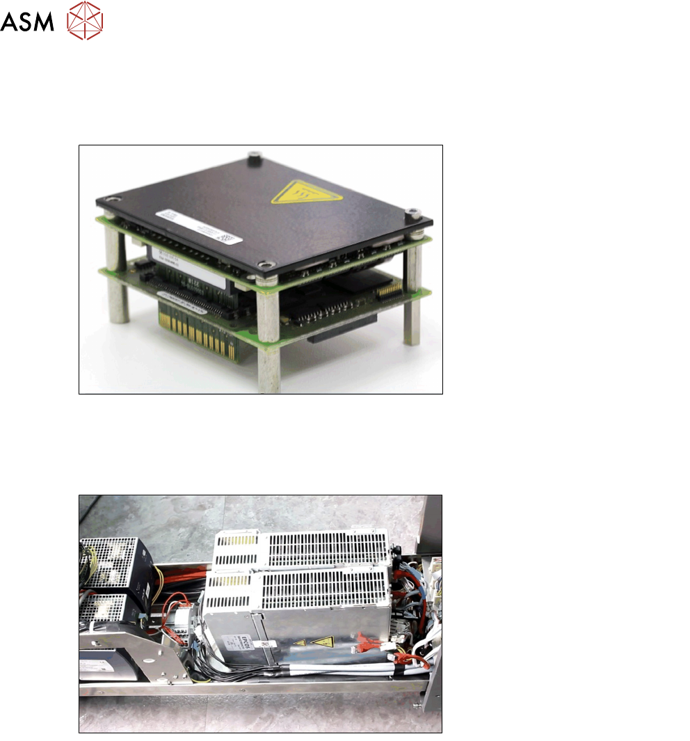
Modular Head Control Unit (MHCU)
The MHCU is used to control the position of the star and Z Axis of C&P20 P and CPP Heads and
also the Twin Head, Z and D Axis (1 MHCU per Twin segment).
It consists of a control module and a power module.
Modular Gantry Control Unit (MGCU)
The MGCU is used to control the position of two main axes within a SIPLACE machine. It consists
of a control module and a power module.
The MGCUs can be found on the power supply unit.
4.5 Control and Communication Overview
Control and Communication Overview
4 Gantry System
4.5 Control and Communication Overview
Technical Training FSE SIPLACE TX-Series 01/2018 43
4 Gantry System
4.5 Control and Communication Overview
44 Technical Training FSE SIPLACE TX-Series 01/2018
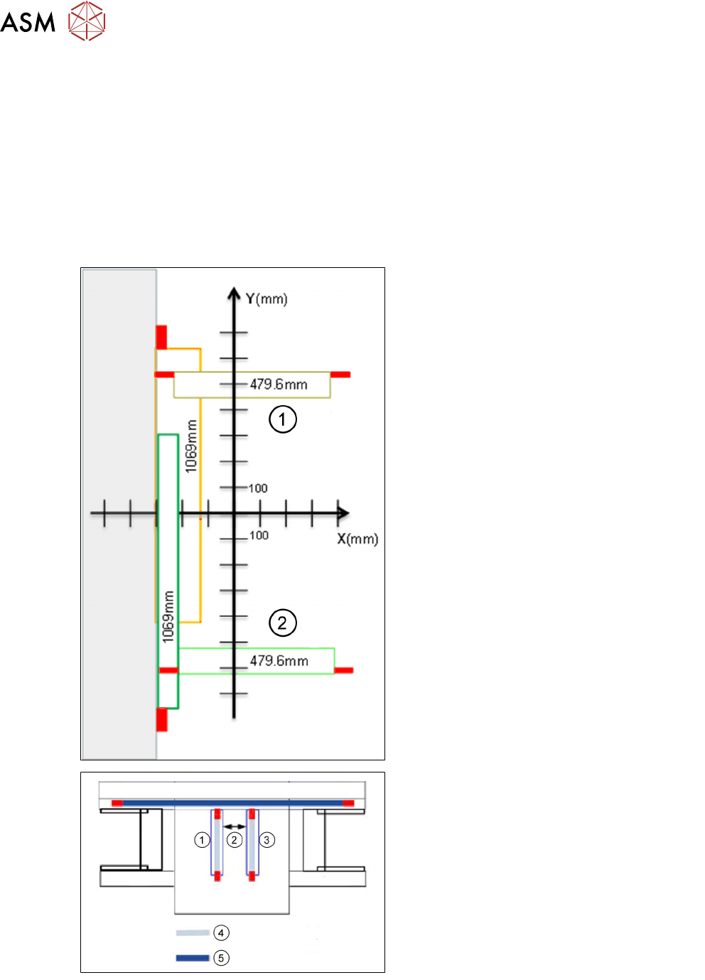
4.5.1 Gantry System - Travel Ranges and Speed Monitoring
Travel ranges and speed monitoring
The travel range of the X/Y Axis will be determined during machine calibration.
●
The end of the X Axis travel range is + or - 0.5 mm before the software limit switch, which is
1.5 mm before the buffer. A safety distance of 2.0 mm to the buffer is adequate if the X Axis
moves into this area with excessive speed.
●
The end of the Y Axis travel range is + or - 2.0 mm before the software limit switch. The Y
Axis travel range for a particular placement area is monitored in one direction by the software
limit switch and a buffer. In the other direction, there is a permanent exchange of communica-
tion between the axes and their positions.
1. Gantry 2
2. Gantry 1
1. Gantry 1
2. Safety distance between the gantries dur-
ing placement. Minimum: 4mm
3. Gantry 2
4. Travel range X
5. Travel range Y