00198171-02_Technical_Training_FSE_TX-Series_EN.pdf - 第64页
6 Conveyor System 6.2 Specification 64 Technical Training FSE SIPLACE TX-Series 01/2018 T - Transport direction 1. Fixture of additional fiducial bar to machine frame 2. Fixture rail on the vacuum tool in Y direc- tion 3…
6 Conveyor System
6.1 Main Overview
Technical Training FSE SIPLACE TX-Series 01/2018 63
6 Conveyor System
6.1 Main Overview
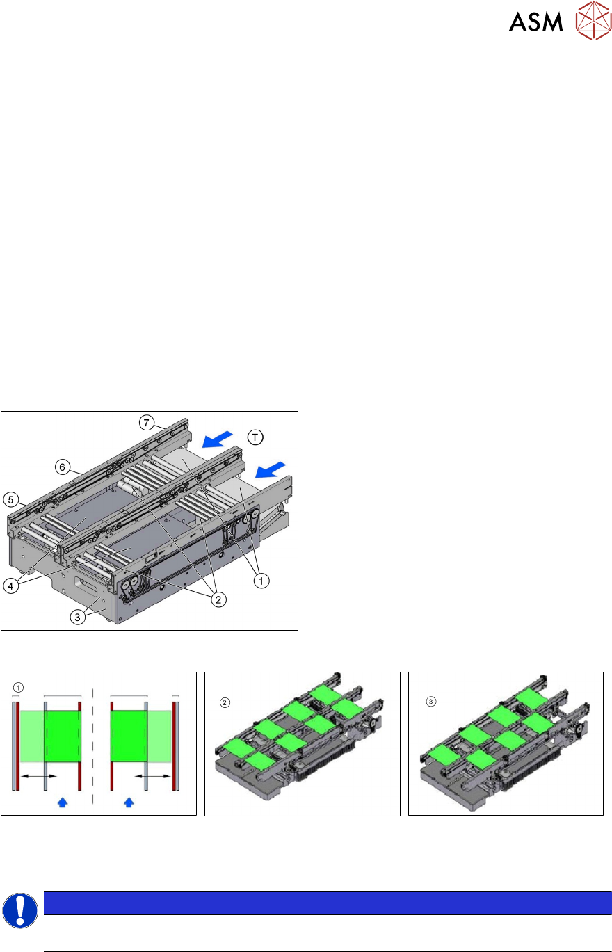
Main Overview TX
●
As standard, the TX machines are set up with dual conveyors and fixed conveyor on the outer
rail. The fixed conveyor left or right side is available as an option.
●
The whole conveyor consists of one part with input (410 mm), placement (PA, 380 mm) and
output (210 mm) sections.
●
The conveyor supports asynchronous and synchronous dual lane mode and I-Placement
mode
●
The conveyor supports the following heights: 900, 930 and 950 mm, standard height is 930
mm.
●
Communication between the PCB conveyors is provided with SMEMA or (optionally)
SIEMENS interface.
●
Input and output conveyor extensions (for barcode scanner, JTF-ML feeder).
1. Transport control board (box)
2. Transport drives
3. Width adjustment motor
4. Lifting table (below lifting motor)
5. Output section (219mm)
6. Placement Area (380mm)
7. Input section (410mm)
T. Transport direction
Conveyor Modes
1. Dual conveyor as single
mode (License required)
2. Synchronous mode op-
tional second sensor in PA
3. Asynchronous mode
with optional second
sensor in PA
NOTICE
If the length of boards is shorter than 175mm, an additional optional light barrier sensor can
be installed for the "Convoy Mode".
Main Overview TX micron
In order to ensure the required accuracy the TX micron conveyor system is slightly different to the
standard TX machine.
6 Conveyor System
6.2 Specification
64 Technical Training FSE SIPLACE TX-Series 01/2018
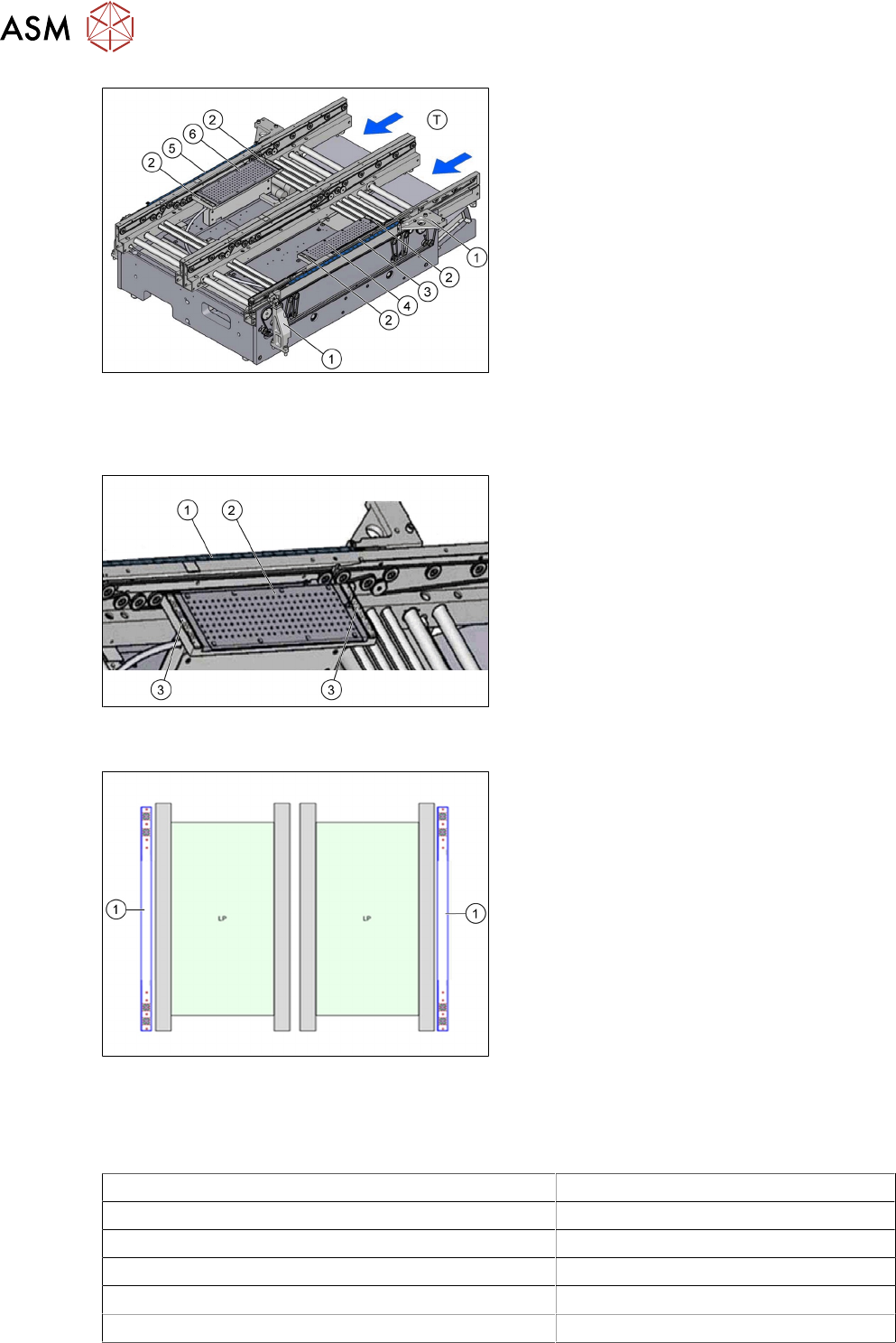
T - Transport direction
1. Fixture of additional fiducial bar to machine
frame
2. Fixture rail on the vacuum tool in Y direc-
tion
3. Additional fiducial bar for lane 2 in X direc-
tion
4. Vacuum tool on lane 2
5. Additional fiducial bar for lane 1 in X direc-
tion
6. Vacuum tool on lane 1
TX micron vacuum tooling
Vacuum tooling SIPLACE TX micron 15µm with Y-fiducial bar. This vacuum tool is necessary to
ensure the accuracy on customer side with the new ACT board (100x250mm).
1. X-fiducial bar
2. Vacuum tooling location
3. Y-fiducial bars
The TX micron machines will be equipped with two X-fiducial bars parallel to the conveyor close
outside of the conveyor rails on the standard conveyor.
1. Two X-fiducial bars used for increased ac-
curacy during placement process.
6.2 Specification
Extract conveyor specification for TX
Dual conveyor standard (L X W) 50 x 45mm to 375mm x 260mm
Dual conveyor single lane mode (L X W) 50 x 45mm to 375mm x 460mm
Standard PCB thickness 0.3 mm to 4.5mm
Maximum PCB weight 2 kg
Clearance below PCB 25 mm
Maximum PCB warpage 2 mm
6 Conveyor System
6.3 Conveyor Functionality
Technical Training FSE SIPLACE TX-Series 01/2018 65
For full specification details see the User Manual delivered with your machine.
Extract conveyor specification for TX micron
Dual conveyor flexible 20µm /25µm (L X W) 50 mm x 55 mm to 375mm x 260mm
Dual conveyor flexible 15µm (L X W) 50 mm x 55 mm to 250mm x 100mm
Dual conveyor single lane mode 20µm /25µm (L X W) 50 mm x 55 mm to 375mm x 460mm
Standard PCB thickness 0.3 mm to 4.5mm
Maximum PCB weight 2 kg
Clearance below PCB 25 mm
Maximum PCB warpage 2.5 mm
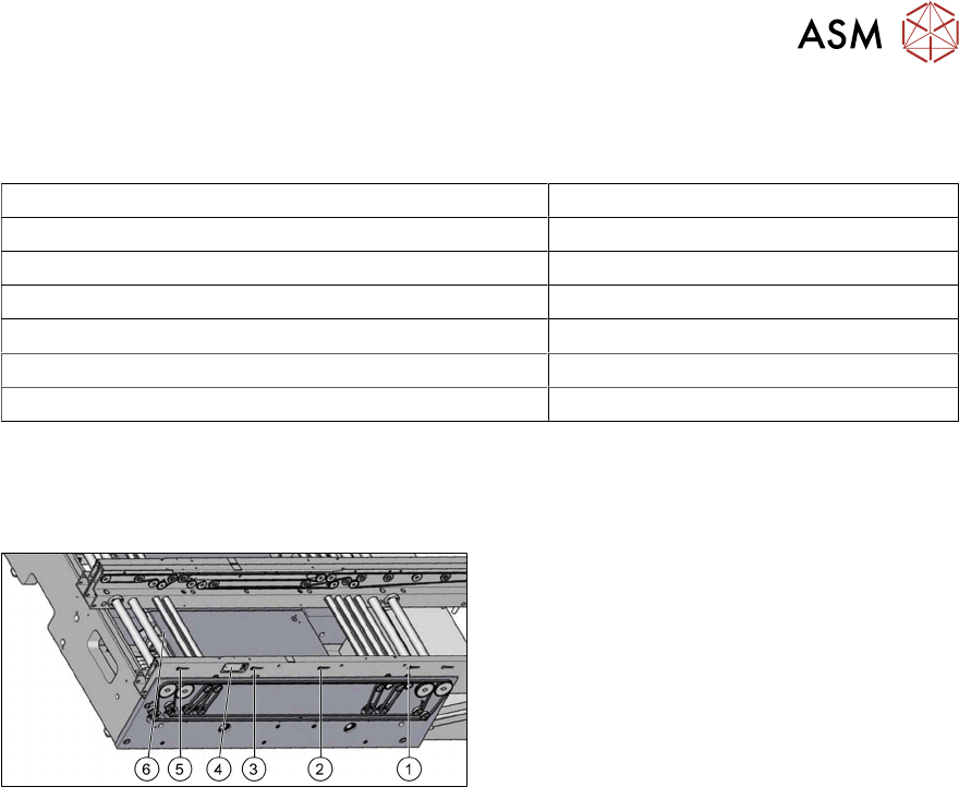
6.3 Conveyor Functionality
6.3.1 TX Board monitoring and clamping
1. Input section light barrier sensor
2. Second light barrier sensor in PA (option)
3. PA light barrier sensor
4. Laser sensor
5. Output section light barrier sensor
6. Amplifier for light barrier sensor
Board recognition
●
Board recognition is monitored and controlled by fiber optic sensors consisting of a control
unit with transmitter and receiver.
●
Each lane has 3 sets of fiber optic sensors in the Input, PA and Output sections.
●
Each lane has one laser beam sensor in PA.
●
Additional fiber optic sensors for second board stop in PA as option.
Board stopping in placement area
●
When the PCB reaches the placement area, the PCB is detected by an interruption to the light
beam and the speed of the conveyor belt is reduced.
●
About 100ms later, a laser beam recognizes the front edge of the slowly approaching board
and the board will be stopped.
Only for machines with vacuum tooling:
●
When the PCB reaches the placement area, the PCB is detected by an interruption to the light
beam on the vacuum tooling.
●
The conveyor belt changes its direction and the PCB is driven backwards and stopped, when
the PCB reaches the in the station SW defined position (value "Offset PCB sensor back-
wards").
●
Afterwards the lifting table (plate) raised and the vacuum is switched on. When the vacuum
value is reached, the placement process can be started.
Board clamping
●
When the board is stopped, the lifting table (plate) is raised by the lifting motor and clamps the
board.
●
Clamping status is checked using the current and encoder system of the conveyor belt motor.
This function is done by the transport control boards.
●
The PCB will be clamped from the bottom side against a fixed edge on the conveyor system.