00198171-02_Technical_Training_FSE_TX-Series_EN.pdf - 第91页
7 Power Supply 7.3 Voltage Overview Block diagrams Technical Training FSE SIPLACE TX-Series 01/2018 91 7.3.3 160 V Intermediate Circuit Voltage for Head Axes The following diagram illustrates the generation of the 160V i…
7 Power Supply
7.3 Voltage Overview Block diagrams
90 Technical Training FSE SIPLACE TX-Series 01/2018
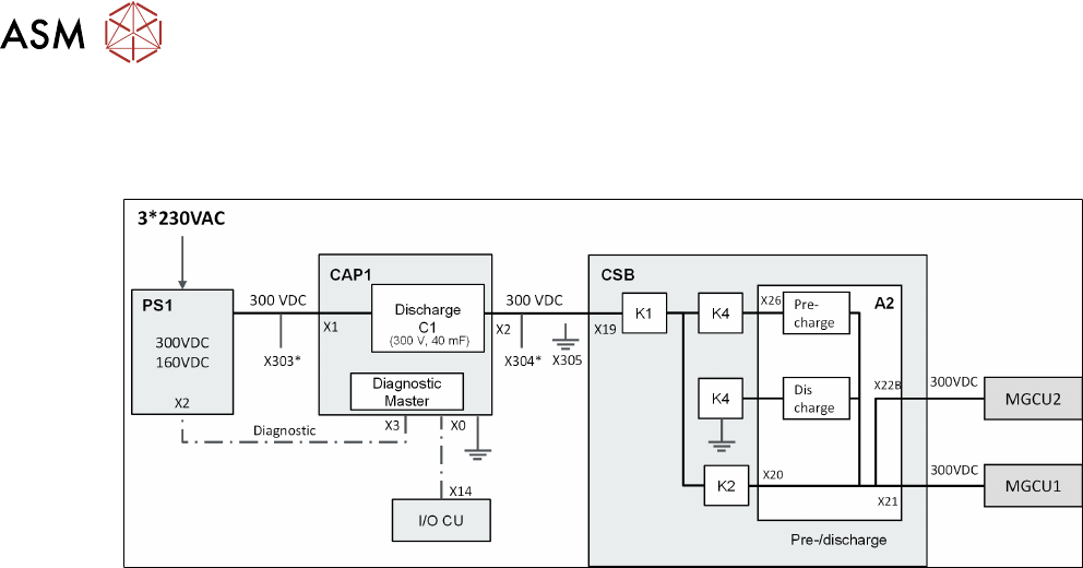
7.3.2 300 V Intermediate Circuit Voltage for Main Axes
The following diagram illustrates the generation of the 300V intermediate circuit current for the
main axes.
* X303/X304 Service Testing point for DC 300V in/out
●
The 300VDC intermediate circuit voltage for the main axes is generated with the PS1 power
pack and is emitted directly via the CAP1 and the CSB assembly to the MGCU.
●
The capacitor battery CAP1 is charged with this 300VDC.
●
The control of pre-charging and discharging of the main axes in connection with the energy
management in the backup battery is managed by the pre/discharge board -A2 in the safety
breaker assembly (CSB).
7 Power Supply
7.3 Voltage Overview Block diagrams
Technical Training FSE SIPLACE TX-Series 01/2018 91
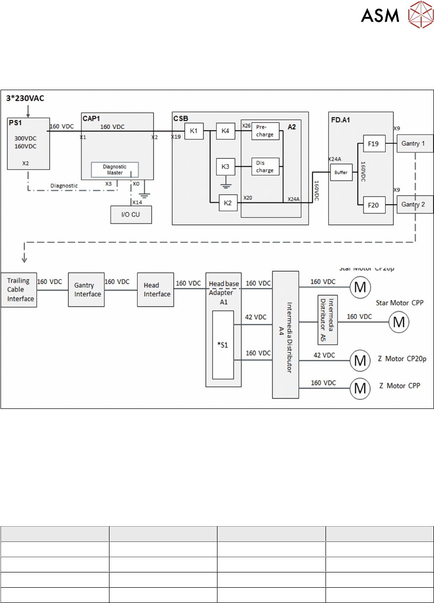
7.3.3 160 V Intermediate Circuit Voltage for Head Axes
The following diagram illustrates the generation of the 160V intermediate circuit current for the
head axes.
*S1 Switch for Intermediate voltage Z Axis, 160V for CPP, 42V for C&P20 P
●
The 160VDC voltage (intermediate circuit) for head axis is not managed via the backup bat-
tery as no energy compensation problems occur here.
●
This voltage runs directly from the power pack PS1 via the backup battery CAP (without func-
tion) to the CSB and is switched there to the pre/discharge board.
●
The head axis voltage is then run via the FDB assembly, protected by fuses there and sent on
to the heads.
Voltage Type Fuse Usage
160 VDC Switched F19 Star Motor gantry 1
160 VDC Switched F19 Z Motor CPP gantry 1
160 VDC Switched F20 Star Motor gantry 2
160 VDC Switched F20 Z Motor CPP gantry 2
7 Power Supply
7.3 Voltage Overview Block diagrams
92 Technical Training FSE SIPLACE TX-Series 01/2018
7.3.4 42 VDC Switched and Unswitched
The following diagram illustrates the generation of the 42V intermediate circuit.
Voltage Type Fuse Usage
42 VDC Unswitched F14 Z Motor CP20 gantry 1
42 VDC Unswitched F15 Z Motor CP20 gantry 2
42 VDC Unswitched F21 Camera illumination (Component & PCB) both
gantry
42 VDC Unswitched F21 Illumination for stationary camera
42 VDC Switched F16 Drive motor for conveyor