00198171-02_Technical_Training_FSE_TX-Series_EN.pdf - 第41页
4 Gantry System 4.4 PCBs Technical Training FSE SIPLACE TX-Series 01/2018 41 4.4 PCBs Head Board Complete (with MHCU) 1. Vision Head Interface (VHI) 2. Head interface 3. Base adapter with MHCU (4) 4. MHCU Base adapter bo…
4 Gantry System
4.3 Calibration after Repair and Adjustment
40 Technical Training FSE SIPLACE TX-Series 01/2018
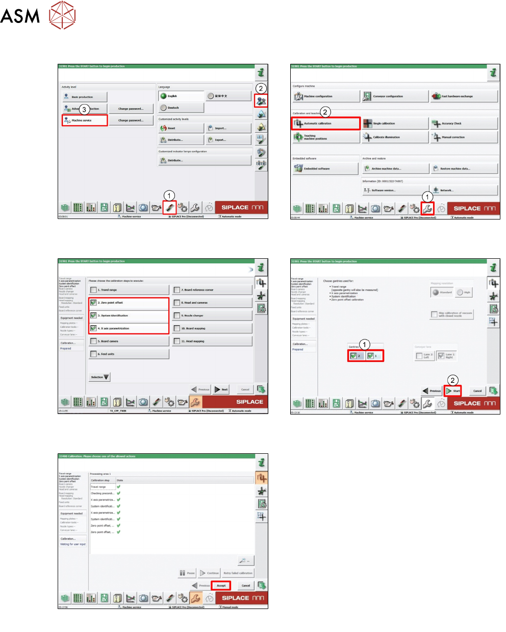
4.3.2 Conducting Calibrations
1. Log on as Machine service (1-3). 2. Click Calibration (1).
Click Automatic calibration (2).
3. Select required calibration item. 4. Select required Gantry (1).
Click Start (2).
5. Click Accept to save data.
4 Gantry System
4.4 PCBs
Technical Training FSE SIPLACE TX-Series 01/2018 41
4.4 PCBs
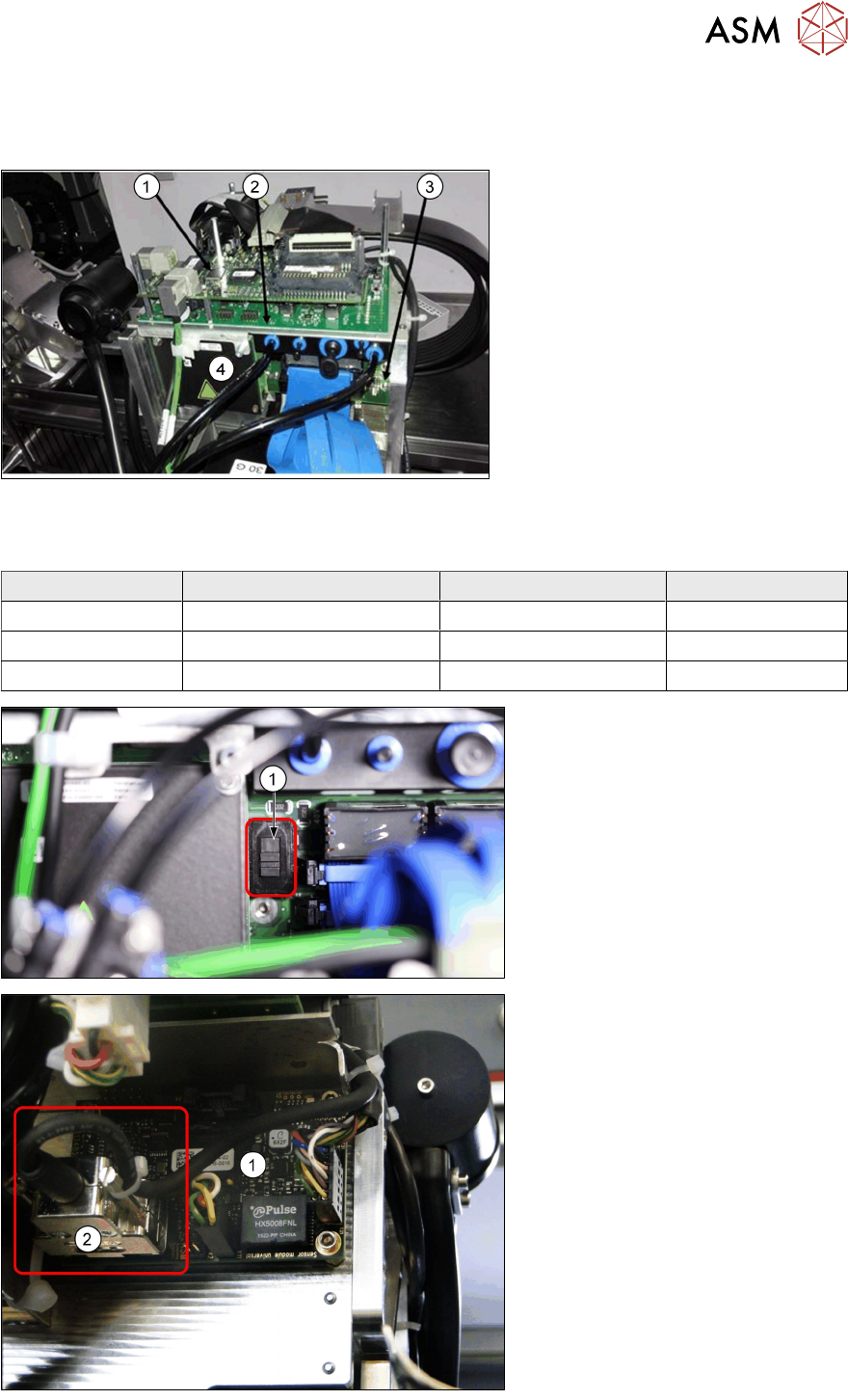
Head Board Complete (with MHCU)
1. Vision Head Interface (VHI)
2. Head interface
3. Base adapter with MHCU (4)
4. MHCU
Base adapter boards
Two kinds of base adapter boards depending on head type.
Head Type Head Interface Base Adapter MHCU
CP20x Head Interface TX (R/L) Base Adapter C&P 1x
CPP Head Interface TX (R/L) Base Adapter C&P 1x
Twin Head Head Interface TX (R/L) Base Adapter TH 2x
Base adapter C&P board
1. "Switch to set the voltage for
ZAxis of CP20x (40V) or CPP
(150V).
1. Sensor module board
2. Plug for reading unit XAxis.
(Micron machines only)
4 Gantry System
4.5 Control and Communication Overview
42 Technical Training FSE SIPLACE TX-Series 01/2018
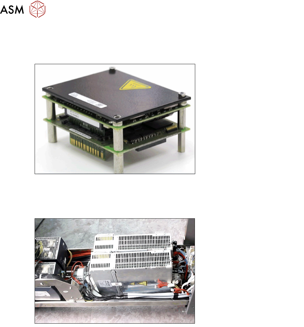
Modular Head Control Unit (MHCU)
The MHCU is used to control the position of the star and Z Axis of C&P20 P and CPP Heads and
also the Twin Head, Z and D Axis (1 MHCU per Twin segment).
It consists of a control module and a power module.
Modular Gantry Control Unit (MGCU)
The MGCU is used to control the position of two main axes within a SIPLACE machine. It consists
of a control module and a power module.
The MGCUs can be found on the power supply unit.
4.5 Control and Communication Overview
Control and Communication Overview