A000062-datasheet.pdf - 第15页
6.4 Power Supply The Arduino Due can be po wered in multiple ways: USB Type-B port (Native port and Pr ogramming port). Using an external voltage sour ce connected to VIN pin, which has a recommended voltage r ange of 7-…
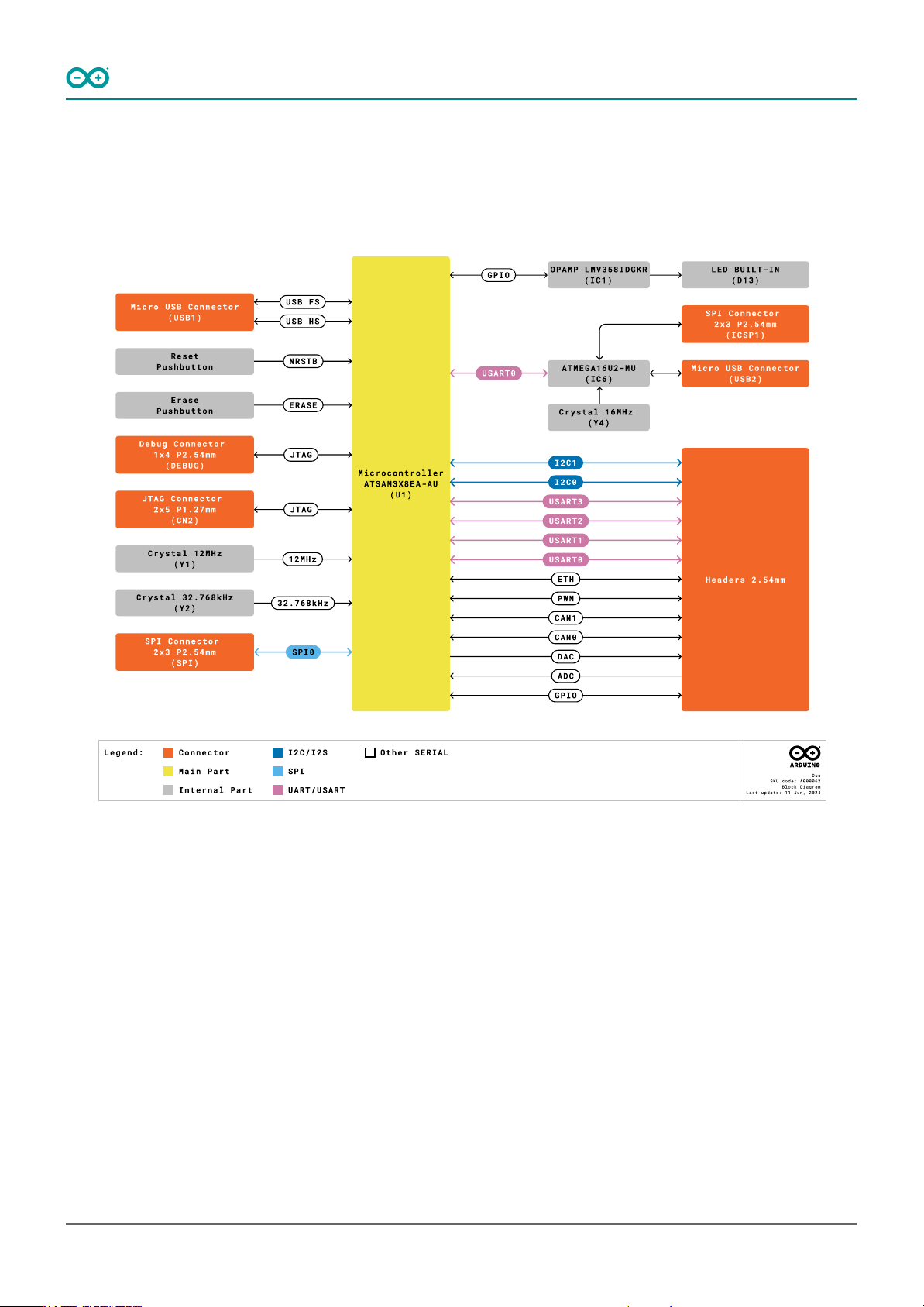
6.3 Block Diagram
The block diagram with the main parts of the product can be checked in the following image:
Arduino Due Block Diagram
Arduino® Due
14 / 50 Arduino® Due Modified: 15/09/2026
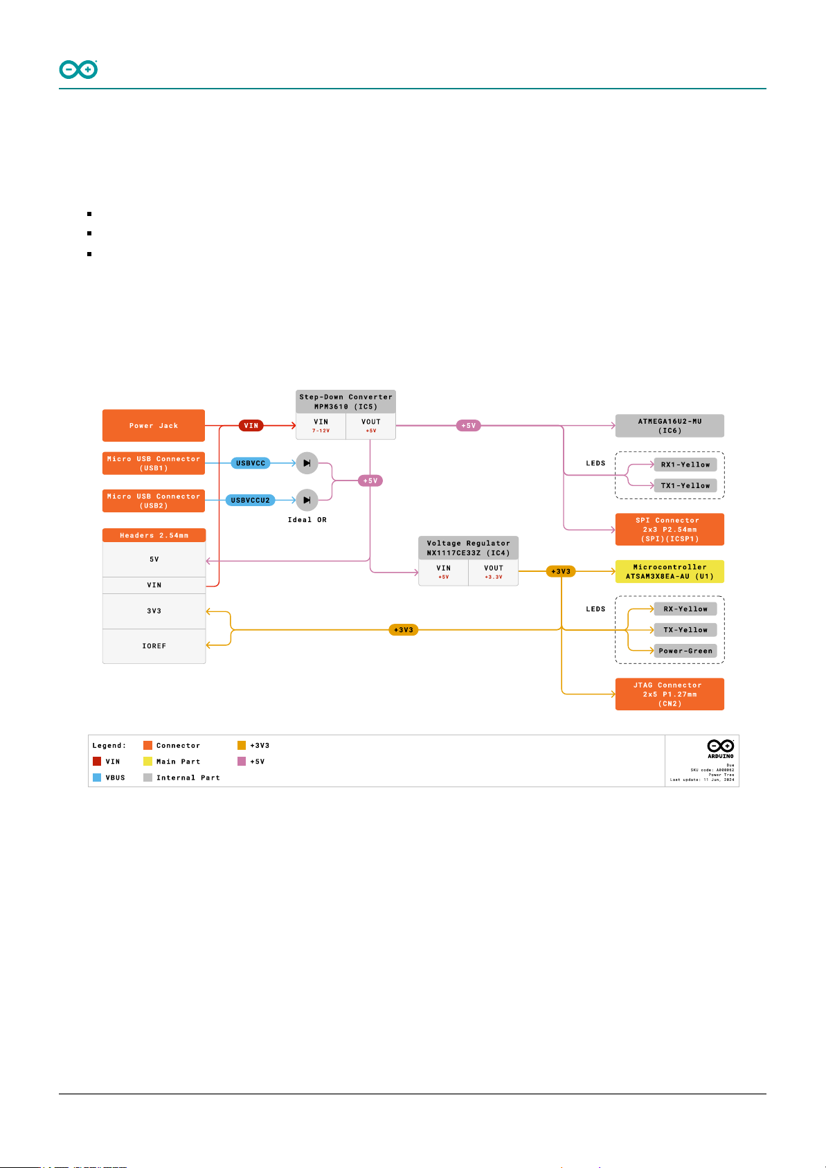
6.4 Power Supply
The Arduino Due can be powered in multiple ways:
USB Type-B port (Native port and Programming port).
Using an external voltage source connected to VIN pin, which has a recommended voltage range of 7-12 VCC.
The Power Jack: The Due can be powered using a DC power supply connected to the power jack, which accepts
a voltage range of 7 to 12 V.
It is essential to note that the Arduino Due operates at 3.3 V, so any external power source must be
regulated to this voltage level. Additionally, the power supply should be able to provide sufficient current
for the board's operation and any connected peripherals.
Arduino Due Power Tree
Arduino® Due
15 / 50 Arduino® Due Modified: 15/09/2026
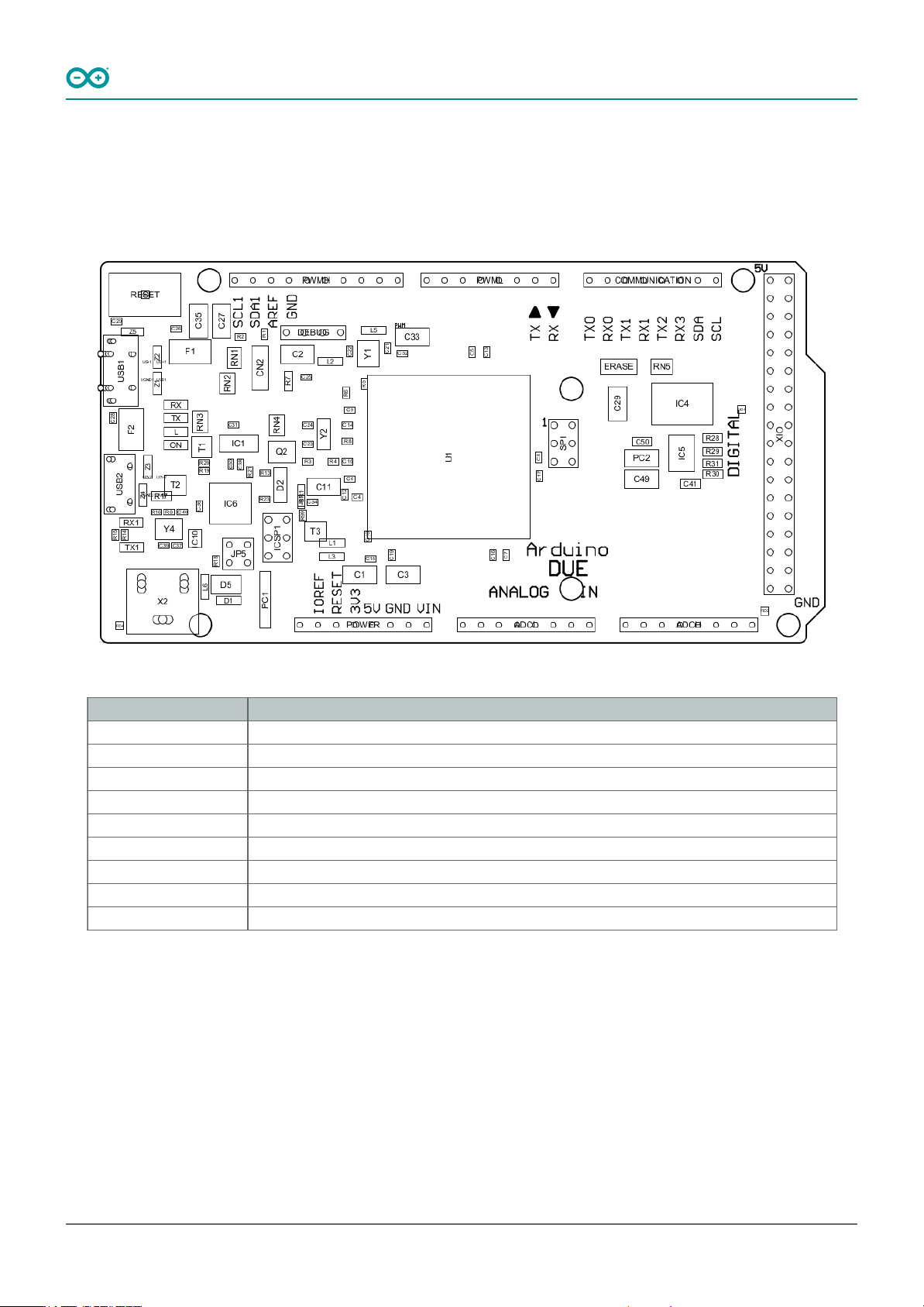
6.5 Product Topology
In the following drawing you can see the main integrated circuits and passive components of the Arduino Due
board.
Arduino Due Topology
Ref. Description
U1 Atmel SAM3X8E ARM Cortex-M3
USB1 Native USB port
USB2 Programming USB port
X2 Power Jack VIN 7-12 VCC
ERASE ERASE Button
RESET Reset Button
DEBUG Debug JTAG pinnout
SPI SPI pinout
ICSP1 ICSPI1 Pinout
Arduino® Due
16 / 50 Arduino® Due Modified: 15/09/2026