A000062-datasheet.pdf - 第17页
6.5.1 JTAG Connector Debugging capabilities are integr ated directly into the Ar duino Due and are accessible via the 6-pin JT A G connector. Pin Function Type Description 1 Reset Reset Reset 2 GND Power GROUND 3 TDI Dig…
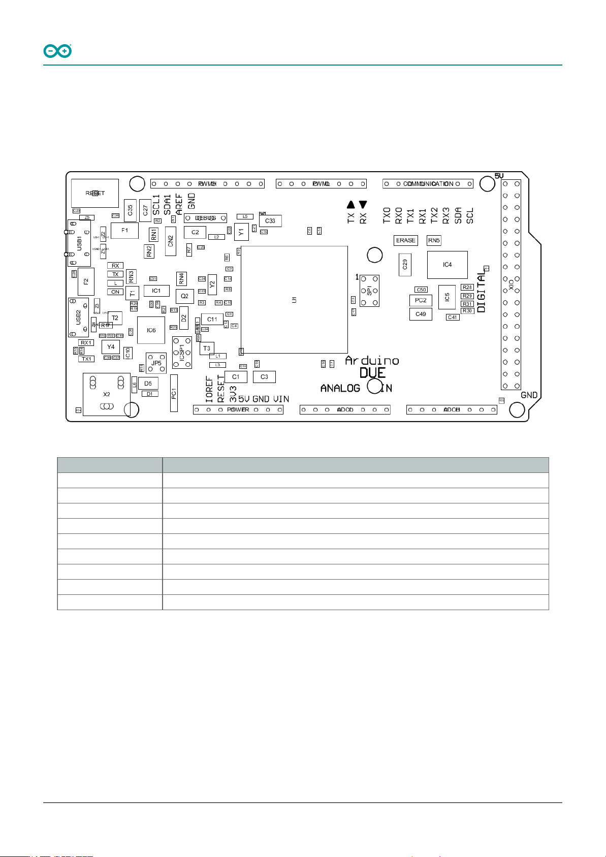
6.5 Product Topology
In the following drawing you can see the main integrated circuits and passive components of the Arduino Due
board.
Arduino Due Topology
Ref. Description
U1 Atmel SAM3X8E ARM Cortex-M3
USB1 Native USB port
USB2 Programming USB port
X2 Power Jack VIN 7-12 VCC
ERASE ERASE Button
RESET Reset Button
DEBUG Debug JTAG pinnout
SPI SPI pinout
ICSP1 ICSPI1 Pinout
Arduino® Due
16 / 50 Arduino® Due Modified: 15/09/2026
6.5.1 JTAG Connector
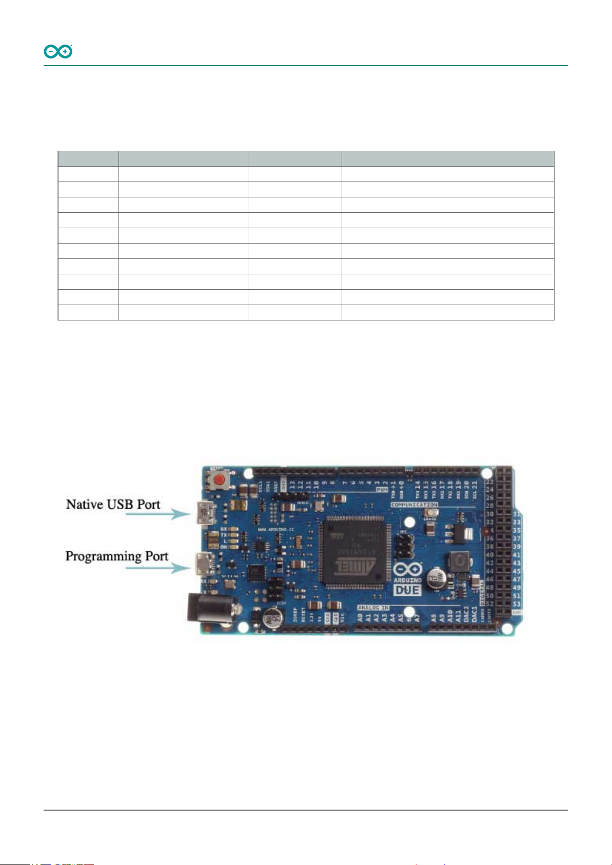
Debugging capabilities are integrated directly into the Arduino Due and are accessible via the 6-pin JTAG connector.
Pin Function Type Description
1 Reset Reset Reset
2 GND Power GROUND
3 TDI Digital Test Data In
4 N/C - Not Connected
5 TDO Digital Test Data Out
6 GND Power GROUND
7 TCK Digital Test Clock
8 GND Power GROUND
9 TMS Digital Test Mode Select
10 +3V3 Power +3V3 Power Rail
JTAG pinout
6.5.2 Native USB Port
The Arduino Due's Native USB port features a USB Type-B connector. This port allows the board to communicate
directly with a computer as a USB device, enabling functionalities such as USB host/device capabilities and USB OTG
(On-The-Go) functionality.
Arduino Due USB port
Arduino® Due
17 / 50 Arduino® Due Modified: 15/09/2026
6.5.3 Programming USB Port
This port allows the board to be programmed and powered via a USB connection to a computer. It facilitates serial
communication between the Arduino Due and the computer, enabling the uploading of sketches and interaction
with the Arduino IDE. The port is connected to the ATmega16U2 microcontroller, which acts as a USB-to-serial
converter, simplifying the programming process. When connected to a computer, the Arduino IDE recognizes the
board as a COM port, enabling seamless communication for programming and debugging purposes.
6.5.4 Board's 24-Pin Header Connector
The 24-pin header connector provides a range of interfaces and general-purpose pins essential for various
applications
These pins offer a range of functionalities, including analog and digital input/output, power supply connections,
analog-to-digital, digital-to-analog conversion and CAN bus communication.
Pin Function Type Description
1 NC NC Not Connected
2 IOREF IOREF Reference for digital logic voltage - connected to 3.3V
3 Reset Reset Reset
4 +3V3 Power +3V3 Power Rail
5 +5V Power +5V Power Rail
6 GND Power Ground
7 GND Power Ground
8 VIN Power Voltage Input
9 A0 Analog Analog input 0 / GPIO
10 A1 Analog Analog input 1 / GPIO
11 A2 Analog Analog input 2 / GPIO
12 A3 Analog Analog input 3 / GPIO
13 A4 Analog Analog input 4 / GPIO
14 A5 Analog Analog input 5 / GPIO
15 A6 Analog Analog input 6 / GPIO
16 A7 Analog Analog input 7 / GPIO
17 A8 Analog Analog input 8 / GPIO
18 A9 Analog Analog input 9 / GPIO
19 A10 Analog Analog input 10 / GPIO
20 A11 Analog Analog input 11 / GPIO
21 DAC0 Analog Digital to Analog Converter 0
22 DAC1 Analog Digital to Analog Converter 1
23 CANRX Digital CAN Bus Receiver
24 CANTX Digital CAN Bus Transmitter
Board's 24-Pin Header pinout
Arduino® Due
18 / 50 Arduino® Due Modified: 15/09/2026