cp842_eng_spec.pdf.pdf - 第10页
Prelim inar y CP-842E/ 842 ME S p ecif icati ons - 8 - 4.2 Nozzles Nozzles are attache d to eac h hea d, with t he follo wing no zzles being availab le for the C P- 842E/842M E. Plate Nozzle diameter Nozzle code *1 Note …
Preliminary CP-842E/842ME Specifications- 7 -
4. Machine Structure
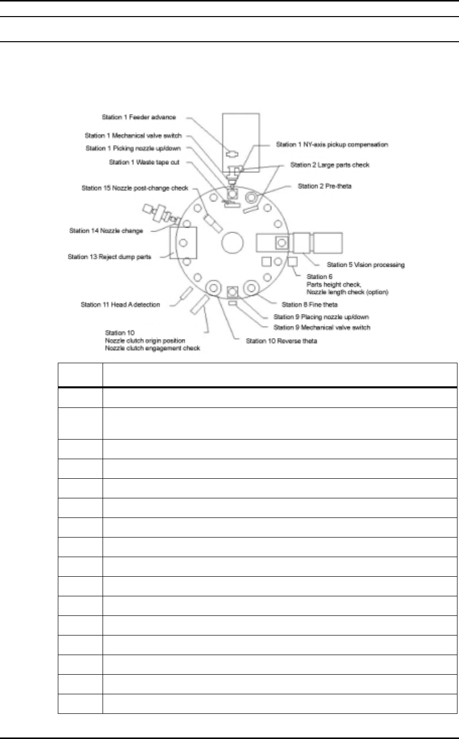
4.1 Placing Head
The function of each of the 16 stations on the turret are detailed below.
St. No. Functions
1 Pick-up part from the device table (Adjustable pick-up height)
2
Large parts pick-up confirmation
Pθ: Placement angle prerotation in 90° angles
3Idle
4Idle
5 Part inspection
6 Measurement of parts height
7Idle
8Fθ: Fine placement angle rotation (including compensation)
9 Placement
10 Rθ: Returns the nozzle to its origin position
11 A-head detection
12 Idle
13 Parts rejection
14 Nozzle change
15 Nozzle change check (detect type No. 1 - 6)
16 Idle
Preliminary CP-842E/842ME Specifications- 8 -
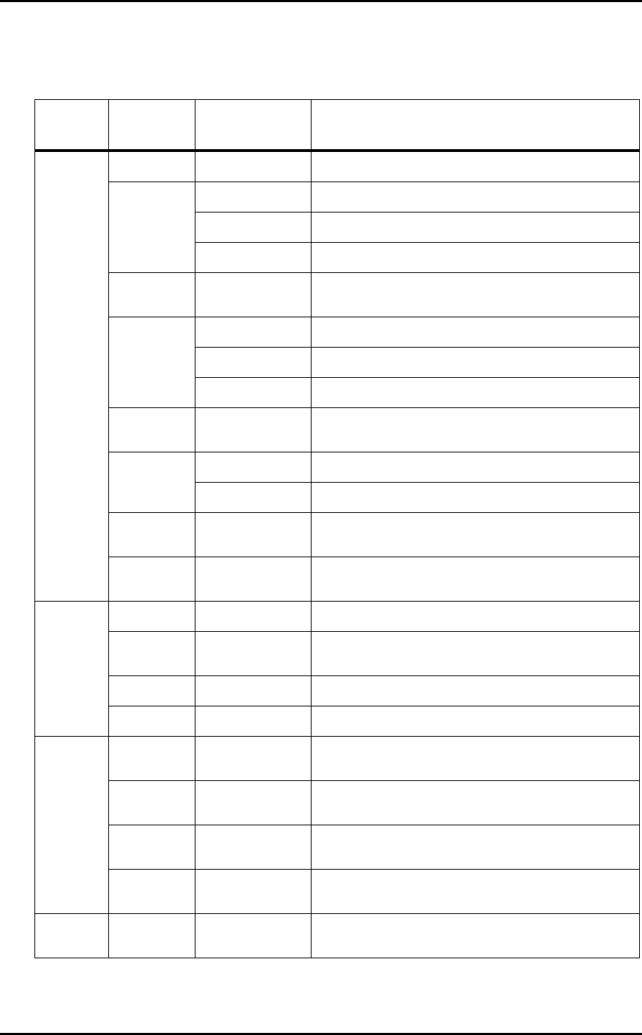
4.2 Nozzles
Nozzles are attached to each head, with the following nozzles being available for the CP-
842E/842ME.
Plate
Nozzle
diameter
Nozzle code
*1
Note
φ
0.27 For 0402 (01005) parts
R08-004
R08-004 Length: 4.5 mm
φ
0.4
R08-004T Tapered nozzle
φ
0.45 KR08-0045T
Supports close-proximity placement (for 0603
(0201))
R08-007
R08-007T Tapered nozzle
φ
0.7
For WL_CSP parts
φ
0.8 KR08-008T
Supports close-proximity placement (for 1005
(0402))
R08-010
φ
1.0
For WL_CSP parts
φ
1.2 KR08-012T
Supports close-proximity placement (for 1608
(0603))
φ
8
φ
1.3
R08-013
M08-013
*2
φ
1.8 R16-018
φ
2.5
R16-025
M16-025
*2
φ
3.7 R16-037
φ
16
φ
5.0 R16-050
φ
1.8
S16-018
B16-018
φ
2.5
S16-025
B16-025
φ
3.7
S16-037
B16-037
16 × 16
(black or
white)
φ
5.0
S16-050
B16-050
21 × 21
(black)
φ
5.0 B21-050
Units: mm

Preliminary CP-842E/842ME Specifications- 9 -
Notes:
1. The meaning of the letters in the “Nozzle code” are detailed below.
R: Round plate (background lighting)
M: Round plate (background lighting, MELF compatible)
T: Round plate (background lighting, tapered nozzle)
K: Supports for close-proximity placement
S: Square plate (background and foreground lighting)
B: Square plate (foreground lighting)
2. Use MELF compatible nozzles for placing MELFs
3. Only a nozzle with a disk diameter of 16 mm or smaller can be positioned next to a
nozzle with a disk size of 16
× 16 mm (black or white). Nozzles with disk sizes of 16 ×
16 mm (black or white) cannot be set at neighboring positions.
Only a nozzle with a disk diameter of 8 mm or smaller can be positioned next to a nozzle
with a disk size of 21
× 21 mm (black).
Nozzles with a diameter of 0.4 mm must be set on the head at any position other than
position 1 (position 6 is recommended).
4. Depending on the shape and weight of the part, a different nozzle may be required.