cp842_eng_spec.pdf.pdf - 第12页
Prelim inar y CP-842E/ 842 ME S p ecif icati ons - 10 - 4.3 Pa rts Supply Table (D-axis) 1. Types of parts CP-842E 140 t ypes (two t ables eac h loade d with s event y 8 mm feeder s) CP-842M E 80 t ypes (t wo tables each…

Preliminary CP-842E/842ME Specifications- 9 -
Notes:
1. The meaning of the letters in the “Nozzle code” are detailed below.
R: Round plate (background lighting)
M: Round plate (background lighting, MELF compatible)
T: Round plate (background lighting, tapered nozzle)
K: Supports for close-proximity placement
S: Square plate (background and foreground lighting)
B: Square plate (foreground lighting)
2. Use MELF compatible nozzles for placing MELFs
3. Only a nozzle with a disk diameter of 16 mm or smaller can be positioned next to a
nozzle with a disk size of 16
× 16 mm (black or white). Nozzles with disk sizes of 16 ×
16 mm (black or white) cannot be set at neighboring positions.
Only a nozzle with a disk diameter of 8 mm or smaller can be positioned next to a nozzle
with a disk size of 21
× 21 mm (black).
Nozzles with a diameter of 0.4 mm must be set on the head at any position other than
position 1 (position 6 is recommended).
4. Depending on the shape and weight of the part, a different nozzle may be required.
Preliminary CP-842E/842ME Specifications- 10 -
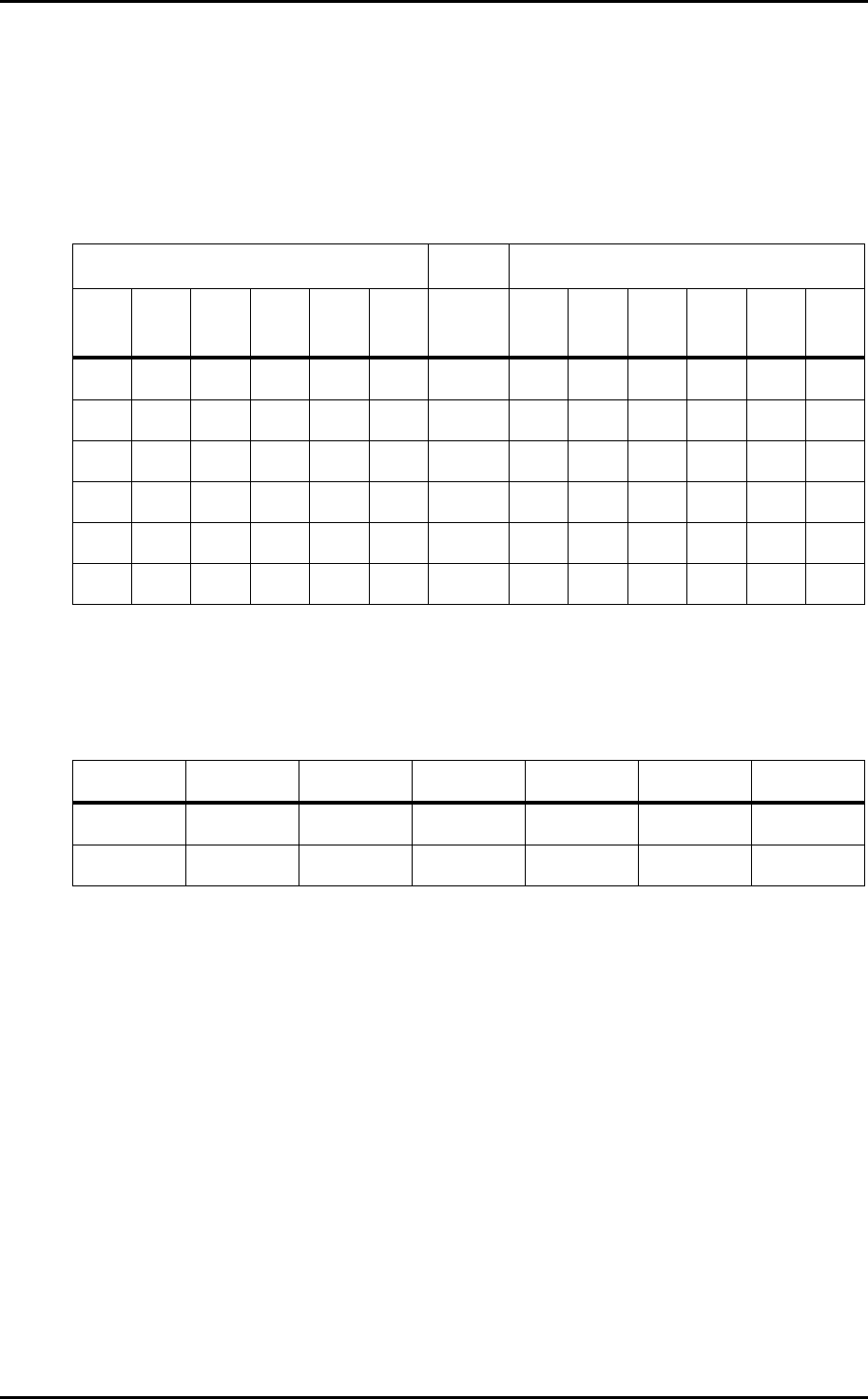
4.3 Parts Supply Table (D-axis)
1. Types of parts
CP-842E 140 types (two tables each loaded with seventy 8 mm feeders)
CP-842ME 80 types (two tables each loaded with forty 8 mm feeders)
2. Table drive method Two motor/two independent drive mechanisms.
3. Feeder Pitch
Left side Ref. Right side
32E 32P 24 16 12 8 W 8 12 16 24 32P 32E
2P 3P 2P 2P 2P 1P 8 1P 2P 2P 2P 2P 2P
3P 3P 2P 2P 2P 2P 12 2P 2P 2P 2P 3P 3P
3P 3P 2P 2P 2P 2P 16 2P 2P 2P 2P 3P 3P
3P 3P 3P 2P 2P 2P 24 2P 2P 2P 3P 3P 3P
3P 3P 3P 3P 3P 2P 32P 3P 3P 3P 3P 3P 3P
3P 3P 3P 3P 3P 2P 32E 2P 3P 3P 3P 3P 3P
Note: The terms “left side” and “right side” refer to the feeder mounting positions when
viewed from the rear of the machine.
4. Feeder Types (which can be placed at the ends of the device tables)
W8 W12 W16 W24 W32P W32E
D1
✔✕✕✕✕✕
D70 (40)
✔✕✕✕✕✕

Preliminary CP-842E/842ME Specifications- 11 -
4.4 Camera Unit
The machine is equipped with two cameras, each camera being used to process different parts.
A high resolution narrow view camera is used to acquire images of small components such as
0603s (0201s), 1005s (0402s) and super small SOTs, and a wide view camera is used for
components such as SOICs, PLCCs and CSPs. The system offers excellent versatility by being
able to change between background or foreground lighting enabling the unit ユ s capability to obtain
a sharp outline of the part, or position parts such as PLCCs by their J-leads and CSPs by their
bumps.
1. Specifications
S_Narrow
*1
Support for 0402
(01005) parts
Narrow Wide
Part size (mm)
0402 (01005) - 2012
(0805), etc.
0603 (0201) - 3216 (1206) 2012 (0805) - 19 × 19
*2
Lighting Foreground and background lighting
Notes:
1. Support for 0402 (01005) parts is available by replacing the lens unit of the narrow view
camera.
2. Background lighting for parts of up to 14
×
14 mm.
2. Supported CSPs
Item Narrow Wide
Max. size Under inspection 19 × 19 mm
Min. bump pitch Under inspection 0.5 mm
Min. bump diameter Under inspection 0.3 mm
Min. bump gap Under inspection 0.2 mm
Orientation check Possible
*1
Possible
*1
Notes:
1. If incorrect orientation is detected, a vision error is issued and the part is rejected.
This function can be used on the condition that bump arrangements are not perfectly
symmetric, all bumps are registered in the part settings, and the bump detection rate is
set to 100%.
2. Detection of missing bumps does not include flattened or deformed bumps.
3. The pitch of at least three bumps in each outer row must be the same.
4. Contact Fuji for information regarding components not listed. Also contact Fuji if a
component body coating (CSP etc.) causes some thickness variation at the component
edges. Such variations may complicate the component inspection process.