cp842_eng_spec.pdf.pdf - 第11页
Prelim inar y CP-842E/ 842 ME S p ecif icati ons - 9 - Notes: 1. The m eaning of the letters in the “ No zzle cod e” are d etail ed bel ow. R: Round pla te (bac kgro und light ing) M: Round pl ate (b ackground light ing,…

Preliminary CP-842E/842ME Specifications- 8 -
4.2 Nozzles
Nozzles are attached to each head, with the following nozzles being available for the CP-
842E/842ME.
Plate
Nozzle
diameter
Nozzle code
*1
Note
φ
0.27 For 0402 (01005) parts
R08-004
R08-004 Length: 4.5 mm
φ
0.4
R08-004T Tapered nozzle
φ
0.45 KR08-0045T
Supports close-proximity placement (for 0603
(0201))
R08-007
R08-007T Tapered nozzle
φ
0.7
For WL_CSP parts
φ
0.8 KR08-008T
Supports close-proximity placement (for 1005
(0402))
R08-010
φ
1.0
For WL_CSP parts
φ
1.2 KR08-012T
Supports close-proximity placement (for 1608
(0603))
φ
8
φ
1.3
R08-013
M08-013
*2
φ
1.8 R16-018
φ
2.5
R16-025
M16-025
*2
φ
3.7 R16-037
φ
16
φ
5.0 R16-050
φ
1.8
S16-018
B16-018
φ
2.5
S16-025
B16-025
φ
3.7
S16-037
B16-037
16 × 16
(black or
white)
φ
5.0
S16-050
B16-050
21 × 21
(black)
φ
5.0 B21-050
Units: mm

Preliminary CP-842E/842ME Specifications- 9 -
Notes:
1. The meaning of the letters in the “Nozzle code” are detailed below.
R: Round plate (background lighting)
M: Round plate (background lighting, MELF compatible)
T: Round plate (background lighting, tapered nozzle)
K: Supports for close-proximity placement
S: Square plate (background and foreground lighting)
B: Square plate (foreground lighting)
2. Use MELF compatible nozzles for placing MELFs
3. Only a nozzle with a disk diameter of 16 mm or smaller can be positioned next to a
nozzle with a disk size of 16
× 16 mm (black or white). Nozzles with disk sizes of 16 ×
16 mm (black or white) cannot be set at neighboring positions.
Only a nozzle with a disk diameter of 8 mm or smaller can be positioned next to a nozzle
with a disk size of 21
× 21 mm (black).
Nozzles with a diameter of 0.4 mm must be set on the head at any position other than
position 1 (position 6 is recommended).
4. Depending on the shape and weight of the part, a different nozzle may be required.
Preliminary CP-842E/842ME Specifications- 10 -
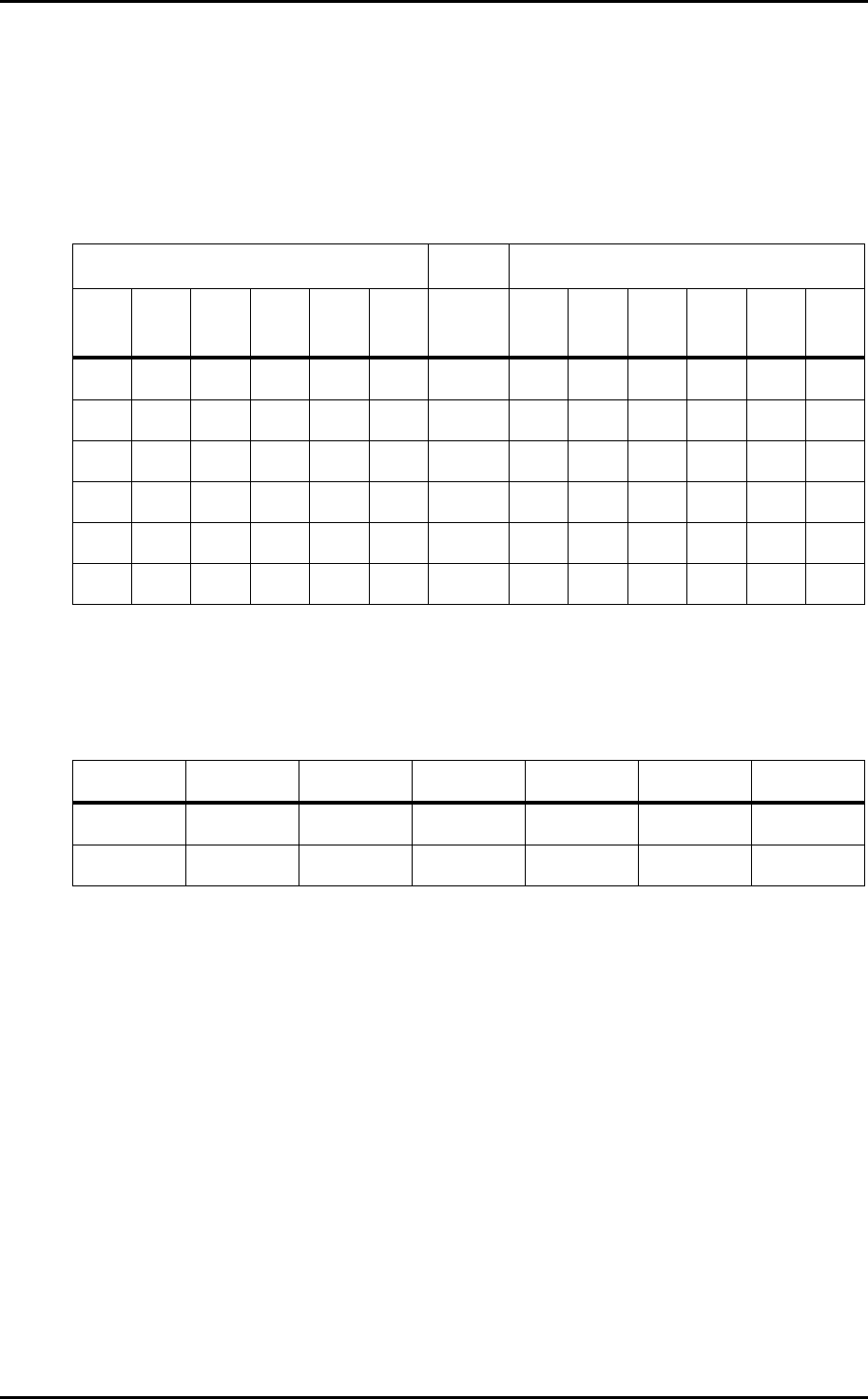
4.3 Parts Supply Table (D-axis)
1. Types of parts
CP-842E 140 types (two tables each loaded with seventy 8 mm feeders)
CP-842ME 80 types (two tables each loaded with forty 8 mm feeders)
2. Table drive method Two motor/two independent drive mechanisms.
3. Feeder Pitch
Left side Ref. Right side
32E 32P 24 16 12 8 W 8 12 16 24 32P 32E
2P 3P 2P 2P 2P 1P 8 1P 2P 2P 2P 2P 2P
3P 3P 2P 2P 2P 2P 12 2P 2P 2P 2P 3P 3P
3P 3P 2P 2P 2P 2P 16 2P 2P 2P 2P 3P 3P
3P 3P 3P 2P 2P 2P 24 2P 2P 2P 3P 3P 3P
3P 3P 3P 3P 3P 2P 32P 3P 3P 3P 3P 3P 3P
3P 3P 3P 3P 3P 2P 32E 2P 3P 3P 3P 3P 3P
Note: The terms “left side” and “right side” refer to the feeder mounting positions when
viewed from the rear of the machine.
4. Feeder Types (which can be placed at the ends of the device tables)
W8 W12 W16 W24 W32P W32E
D1
✔✕✕✕✕✕
D70 (40)
✔✕✕✕✕✕