00193437-03_AI_PowerSupplyConversion_DE+EN.pdf - 第202页
5 Converting the power supply on S-27 HM machines/ and on component trolleys Assembly Instructions, Converting the Power Supply 5.7 Converting the component trolley from 230 VAC to 120 VAC 12/2013 Edition 200 5.7.1 Conve…
Assembly Instructions, Converting the Power Supply 5 Converting the power supply on S-27 HM machines/ and on component trolleys
12/2013 Edition 5.7 Converting the component trolley from 230 VAC to 120 VAC
199
5.7 Converting the component trolley from 230 VAC to 120 VAC
RISK OF DEATH 5
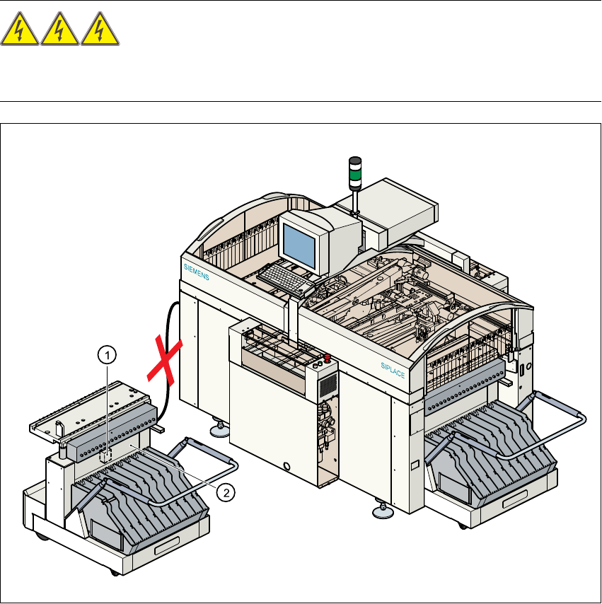
The component trolley must be docked out during the rewiring work. The power cable and com-
munication cable must both be unplugged. 5
Fig. 5 - 6 Component trolley, transformer T1
(1) Transformer T1
(2) Top part of frame
5 Converting the power supply on S-27 HM machines/ and on component trolleys Assembly Instructions, Converting the Power Supply
5.7 Converting the component trolley from 230 VAC to 120 VAC 12/2013 Edition
200
5.7.1 Converting transformer T1 from 230 VAC to 120 VAC
Transformer T1 (item 1 in Fig. 5 - 6) can be accessed from beneath the top part of the frame
(item 2 in Fig. 5 - 6
). 5
Loosen the four hexagon socket-head screws.
Pull the cover plate over the transformer housing down and off.
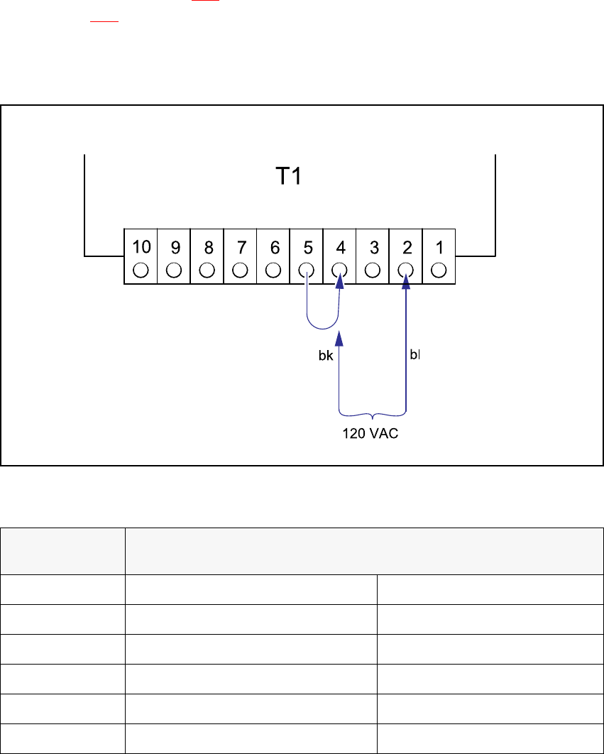
Fig. 5 - 7 Changeover table, transformer T1, terminals
5
5
Detach the black wire from terminal 5 and connect to terminal 4.
Voltage
Terminals
Blue wire Black wire
242 VAC 1 5
230 VAC 2 5
219 VAC 3 5
126 VAC 1 4
120 VAC 2 4
114 VAC 3 4
Tab. 5 - 1 Changeover table, supply voltages for transformer T1

Assembly Instructions, Converting the Power Supply 5 Converting the power supply on S-27 HM machines/ and on component trolleys
12/2013 Edition 5.7 Converting the component trolley from 230 VAC to 120 VAC
201
5.7.2 Replacing the fuse
There are two versions of the main power supply for the component trolley: 5
Replacing the fuse F1 on the old power supply 5
Here, the fuse is located on the primary side of transformer T1. The fuse F1 must be replaced (see
circuit diagram 00301239-040301LD4, page 212
) 5
Replace the fuse in the fuse holder in the cover panel:
old rating: 3.15 A T
new rating: 6.3 A T
Replace the adhesive label specifying 3.15 A with the 6.3 A label from the conversion kit.
Replace the cover panel over the transformer and tighten the four hexagon socket-head
screws.
New power supply 5
Here there are two fuses on the secondary side of transformer T1. The fuses do not have to be
replaced (see circuit diagram 00301239-060101LD4, page 213
) 5
Replace the cover panel over the transformer and tighten the four hexagon socket-head
screws.
5.7.3 Checking the protective earth wire connections
Check that the detached protective earth wires have been reconnected correctly.
5.7.4 Carry out the safety check to DIN EN 60 204
When the conversion is complete, carry out a safety check to DIN EN 60 204.
Follow the procedure described in section 2, page 146 onwards.