00198168-02_Technical_Training_TX-Series_EN.pdf - 第133页
5 Placement Heads 5.3 Twin Head Technical Training SIPLACE TX-Series 10/2016 133 5.3.2 Reference Run The Twin Head consists of two segments which have two axes Z and D and the X and Y Axes at the gantry. Before reference…
5 Placement Heads
5.3 Twin Head
132 Technical Training SIPLACE TX-Series 10/2016
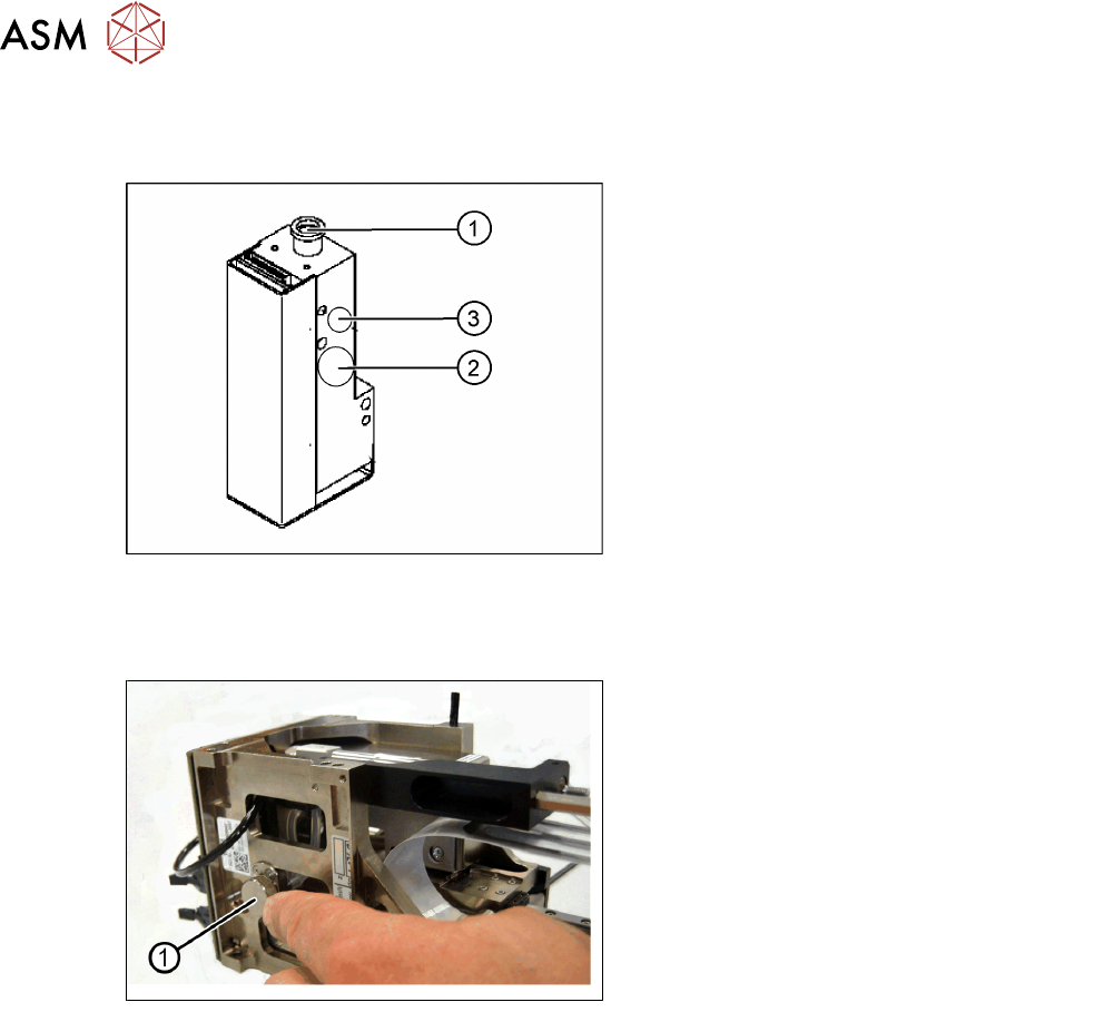
5.3.1.3 Main Parts / Unit Overview
Twin Head – Pressure Regulator Valve (PRV)
1. Compressed air connection
2. Output vacuum is passed through the D
Axis motor shaft and on to the nozzle
3. Discharged air for cooling the X linear
motor
The PRV automatically controls the vacuum, air blast and the zero balancing position (middle
position-→ no vacuum and no air blast) for the segments.
Twin Head – Filter
1. Filter for the vacuum system.
The Filter is mounted on the return unit and
used as an attenuator to control the vacuum.
The filter with the additional volume reduces the oscillation of the vacuum generator and
guarantees an accurate vacuum and air blast supply.
The filter is serviced at regular intervals, which must be adhered to (see maintenance Job Card).
5 Placement Heads
5.3 Twin Head
Technical Training SIPLACE TX-Series 10/2016 133
5.3.2 Reference Run
The Twin Head consists of two segments which have two axes Z and D and the X and Y Axes at
the gantry.
Before reference run the return cylinder is moved out to the lower home position. On both modules
the vacuum is on until the PRV is initialized.
The Twin Head reference run is performed parallel to the C&P Heads reference run.
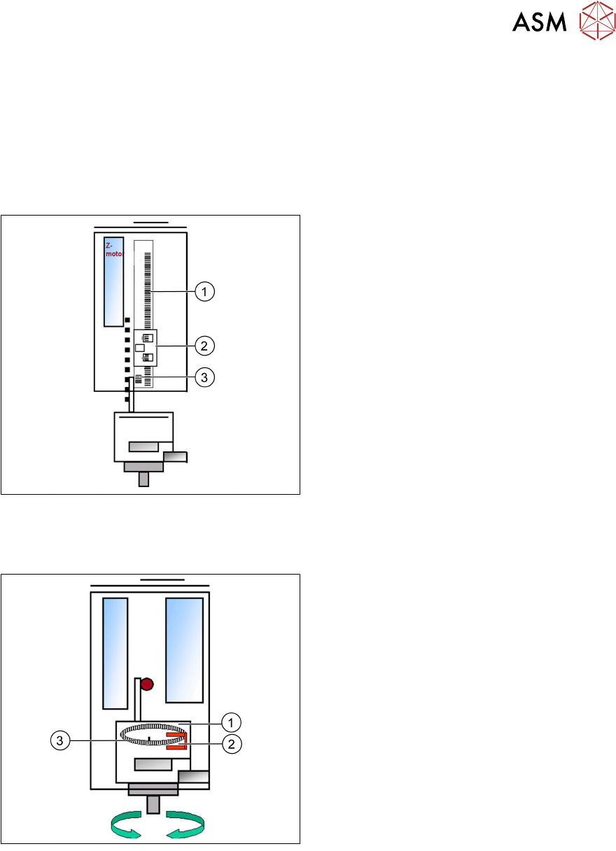
Reference Run: Z Axis
1. Incremental scale mounted on moveable
part of the Z Axis
2. Fixed Incremental encoder
3. Zero pulse on the incremental scale
●
Z Axis search for the commutation point of
the linear motors (special mode due risk of
a movement downwards).
●
Then the Z Axis move upwards to the Zero
pulse and load the zero point correction.
●
Then the Z Axis move upwards to the Zero
pulse and load the zero point correction.
The zero point correction, max. and min. travel range are determined when you calibrate the head
height.
Reference Run: DP Axis
1. Incremental glass scale D Axis
2. Incremental encoder
3. Zero pulse on the incremental glass scale
●
The D Axis runs to the zero pulse of the D
Axis encoder.
●
The zero point correction value will be
loaded.
●
The D Axis moves to the reference
position.
5 Placement Heads
5.3 Twin Head
134 Technical Training SIPLACE TX-Series 10/2016
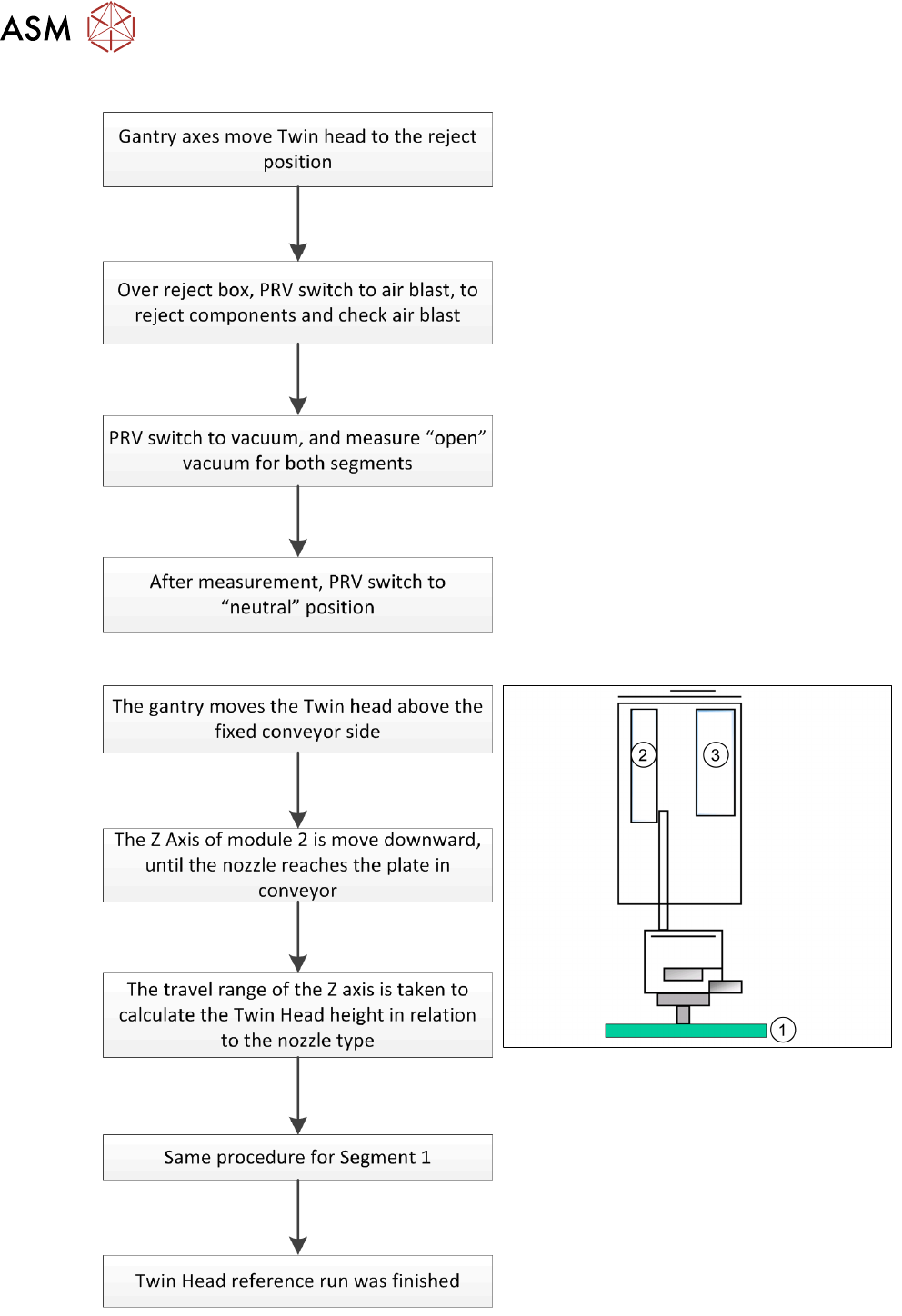
Reference Run: Vacuum Check
After the processor for the PRV has booted, the
PRV is initialized. This means that neither
vacuum nor air blast is generated at the nozzle.
Note: The “closed” vacuum value for the Twin
segments relates to the calibration value.
Reference Run: Height Of Nozzle
1. Top of fixed conveyor side
2. Z Motor
3. Vacuum - air blast distribution
With this function we check that the
programmed nozzle type is on the segment.
The nozzle length is taken to calculate the pick
up and placement height for the following
placements.