00198168-02_Technical_Training_TX-Series_EN.pdf - 第142页
5 Placement Heads 5.3 Twin Head 142 Technical Training SIPLACE TX-Series 10/2016 Twin Head – Main Board Description LEDs LEDs (2) Description (Sequence Downwards) LED Color Description D8 Green Off – retract unit is move…
5 Placement Heads
5.3 Twin Head
Technical Training SIPLACE TX-Series 10/2016 141
5.3.6 Board Description
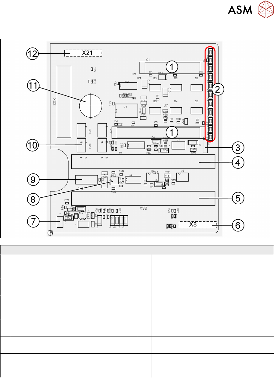
Twin Head – Main Board Description Connectors
1 2 connectors for the 16 bit CAN Bus
processor (not used)
7 Power supply 15V for the Track signals
D- Axis (at the moment deactivated via the
jumper X54)
2 LEDs (see below) 8 EEPROM stores the head specific data
(head exchange, reference run)
3 X54 Jumper currently set to ON with the
new force measurement board set to OFF
(see LED V2/V_SP)
9 X4 Connector track signals Z Axis
4 Connector to the head adapter flat ribbon
cable
10 Connector pneumatic valve (retract unit)
5 Connector to the head adapter flat ribbon
cable
11 Hole for pneumatic pipe to the vacuum
generator
6 X8: Flex-Cable (Signals: Track signals
D Ax- is, Power supply Z Axis/D Axis, Z
Temperature and, SPI Bus)
12 X21 Connector for vacuum generator
5 Placement Heads
5.3 Twin Head
142 Technical Training SIPLACE TX-Series 10/2016
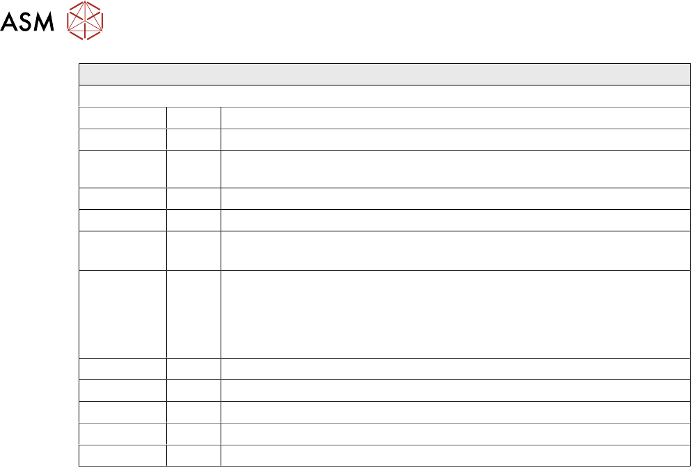
Twin Head – Main Board Description LEDs
LEDs (2) Description (Sequence Downwards)
LED Color Description
D8 Green Off – retract unit is moved out – LED shines briefly
D7 KLEMM Green On - display showing that the return cylinder has been projected
downwards.
D6 BERO Green Off - without function (previously: proximity switch Z Axis up)
D1 DRUCK Yellow Off - without function (Z pressure)
D2 KLEMM Yellow On – clamping Z Axis
Off – retract unit is at top position
V2/V_SP Green Shows the voltage supply 15 V for the D Axis track signals. Off – at jumper
setting ON and old force measurement board.
On – Twin Heads with new force measurement board have the 15V
regulated on the main board i.e. the jumper must be set to OFF and the
LED will be on.
V3 15V_ Green On – 15V for the D Axis track signals
V1 TEMP Green On - Z Axis motor temperature is OK
D14 ALARM Red Off – alarm output for vacuum generator On – vacuum generator defect
D9 DRUCK Green Off - without function (Z pressure)
D10 24V+ Green On – 24V for vacuum generator is OK
5 Placement Heads
5.3 Twin Head
Technical Training SIPLACE TX-Series 10/2016 143
5.3.7 Calibration
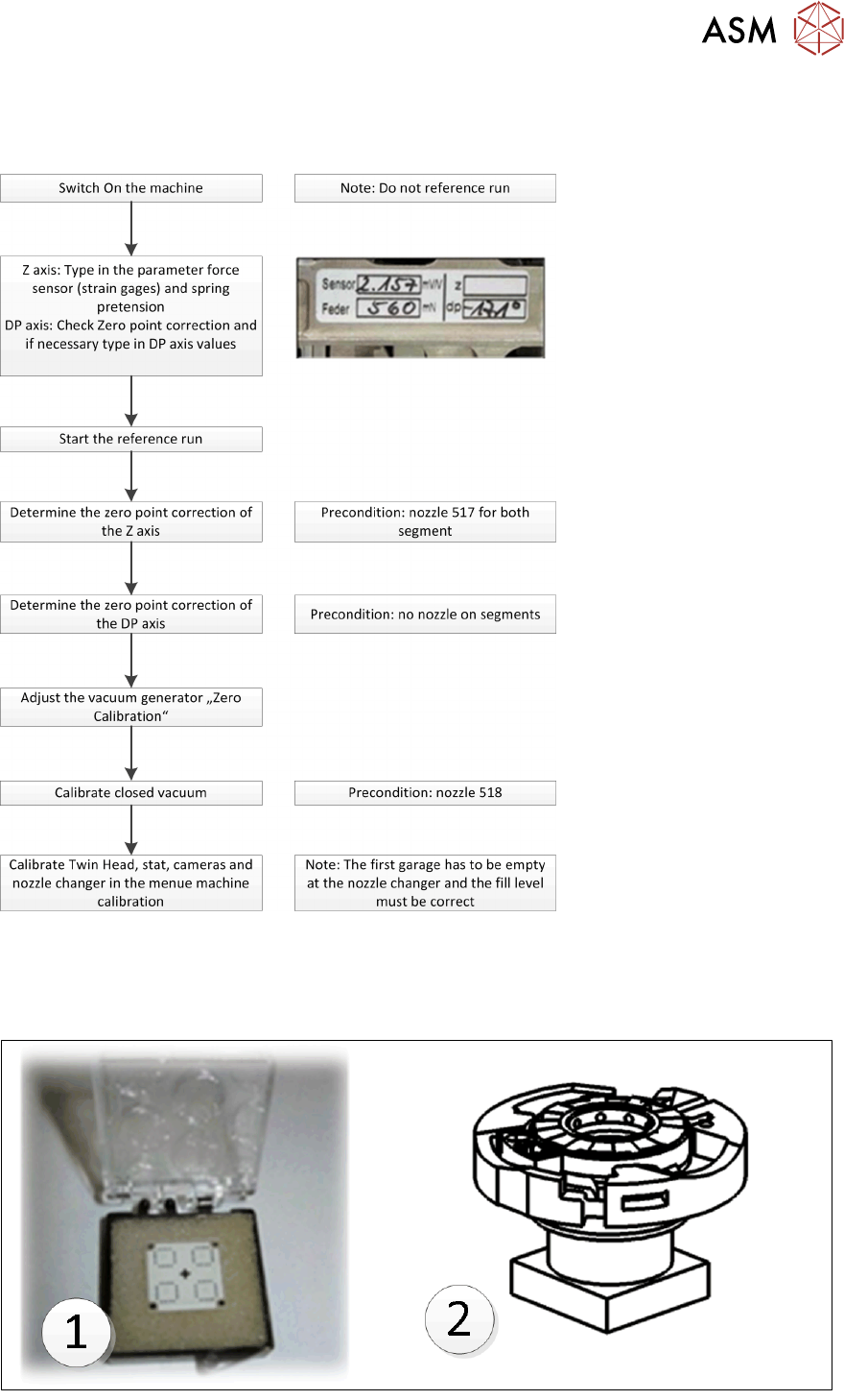
Twin Head – Calibration Overview
Twin Head Calibration Tools & Nozzle
Calibration tool 03010565 xx (1) - & Nozzle 517 / 518 for Head Calibration.
Calibration tool 03123022-xx (2) is required when calibrating the D-Axis zero point correction of
Twin Head using a Flip Chip Camera