00198168-02_Technical_Training_TX-Series_EN.pdf - 第141页
5 Placement Heads 5.3 Twin Head Technical Training SIPLACE TX-Series 10/2016 141 5.3.6 Board Description Twin Head – Main Board Description Connectors 1 2 connectors for the 16 bit CAN Bus processor (not used) 7 Power su…
5 Placement Heads
5.3 Twin Head
140 Technical Training SIPLACE TX-Series 10/2016
5.3.5 Handling
Twin Head – Lowering the Z Axis
Manual Lowering of Z Axis
The Twin Head is designed for a placement force of 1.0 to 15N.
The Z Axis needs to be very smooth-running, especially for low placement forces. Therefore, the
ZAxis has to be handled carefully.
Cause of Hazard
When manually lowering the Z Axis, the Twin Head module can be easily damaged!
●
Manual lowering may only be done.
Before performing manual lowering of the Z Axis, make sure the Z Axis has been released.
●
When releasing the ZAxis, the ZAxis return cylinder moves upwards.
●
If the axis is not released, the return cylinder will automatically move upwards when the ZAxis
is manually lowered, which could cause injuries and damage to the placement head.
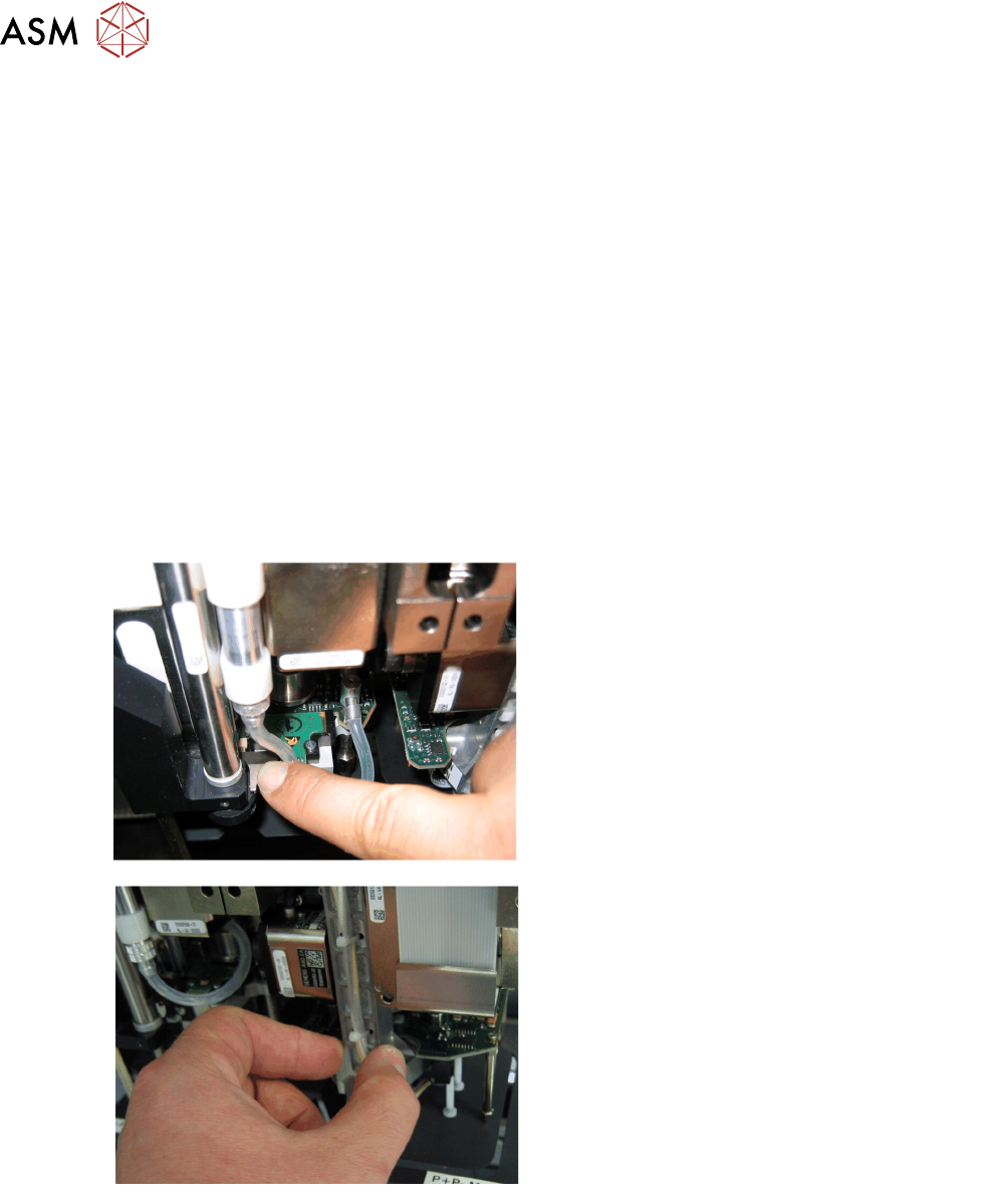
Lowering the Z Axis
Lowering the ZAxis at P&P Module1
To safely press the ZAxis downwards, apply
manual pressure to the marked part of the retract
unit driver.
Lowering the ZAxis at P&P Module2
The ZAxis can be moved downwards at segment
2 by taking hold of the carrier arm from both
sides and then pushing this down.
5 Placement Heads
5.3 Twin Head
Technical Training SIPLACE TX-Series 10/2016 141
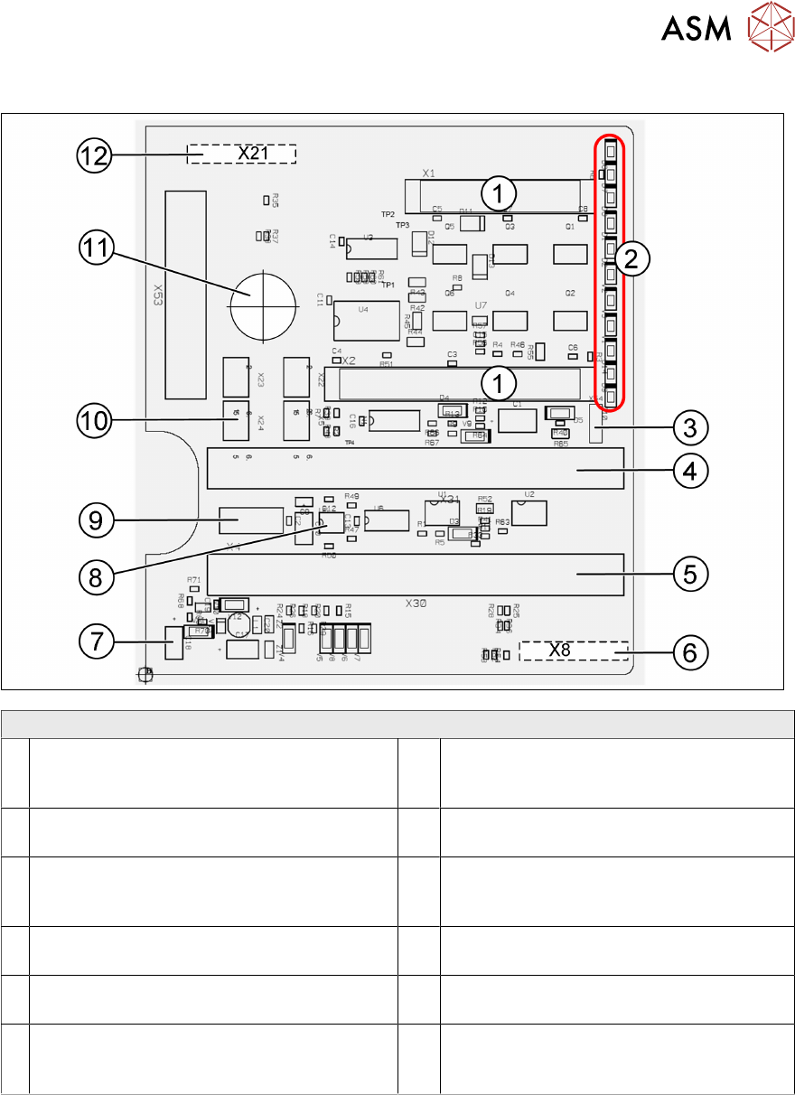
5.3.6 Board Description
Twin Head – Main Board Description Connectors
1 2 connectors for the 16 bit CAN Bus
processor (not used)
7 Power supply 15V for the Track signals
D- Axis (at the moment deactivated via the
jumper X54)
2 LEDs (see below) 8 EEPROM stores the head specific data
(head exchange, reference run)
3 X54 Jumper currently set to ON with the
new force measurement board set to OFF
(see LED V2/V_SP)
9 X4 Connector track signals Z Axis
4 Connector to the head adapter flat ribbon
cable
10 Connector pneumatic valve (retract unit)
5 Connector to the head adapter flat ribbon
cable
11 Hole for pneumatic pipe to the vacuum
generator
6 X8: Flex-Cable (Signals: Track signals
D Ax- is, Power supply Z Axis/D Axis, Z
Temperature and, SPI Bus)
12 X21 Connector for vacuum generator
5 Placement Heads
5.3 Twin Head
142 Technical Training SIPLACE TX-Series 10/2016
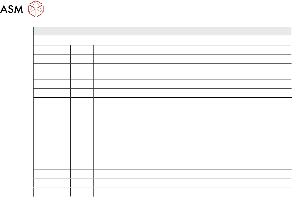
Twin Head – Main Board Description LEDs
LEDs (2) Description (Sequence Downwards)
LED Color Description
D8 Green Off – retract unit is moved out – LED shines briefly
D7 KLEMM Green On - display showing that the return cylinder has been projected
downwards.
D6 BERO Green Off - without function (previously: proximity switch Z Axis up)
D1 DRUCK Yellow Off - without function (Z pressure)
D2 KLEMM Yellow On – clamping Z Axis
Off – retract unit is at top position
V2/V_SP Green Shows the voltage supply 15 V for the D Axis track signals. Off – at jumper
setting ON and old force measurement board.
On – Twin Heads with new force measurement board have the 15V
regulated on the main board i.e. the jumper must be set to OFF and the
LED will be on.
V3 15V_ Green On – 15V for the D Axis track signals
V1 TEMP Green On - Z Axis motor temperature is OK
D14 ALARM Red Off – alarm output for vacuum generator On – vacuum generator defect
D9 DRUCK Green Off - without function (Z pressure)
D10 24V+ Green On – 24V for vacuum generator is OK