Covers.pdf - 第28页
COVERS MACHINE COVERS 3.28 Technical Reference Manu al Chapter Issue 2 Sep 09
COVERS
MACHINE COVERS
3.26 Technical Reference Manual Chapter Issue 2 Sep 09
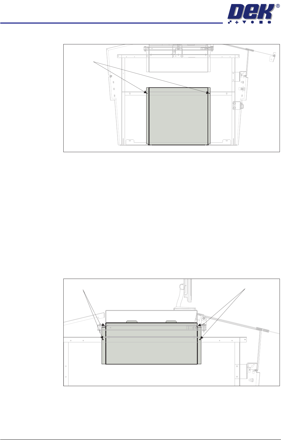
8. Remove the two M5 cap head screws.
9. Tilt the top of the panel away from the machine and lift the panel clear.
10. Repeat Steps 1 and 6 to 9 for the other lower side panel, if required.
Upper Side Panels To remove the upper side panels, carry out the following:
1. Remove the corresponding safety cover (as detailed previously).
2. Open the front printhead cover.
3. Remove the front panel (as detailed previously).
4. Remove the rear panel (as detailed previously).
5. Remove the rear fixed printhead cover (as detailed previously).
6. Remove the corresponding rear corner panel (as detailed previously).
7. Remove the corresponding front corner panel (as detailed previously).
8. Remove the four M5 cap head screws.
9. Tilt the bottom of the panel away from the machine and lift the panel clear.
10. Repeat Steps 1 and 6 to 9 for the other upper side panel, if required.
View on Left Hand Side of Machine
M5 Cap Head
Screws
View on Left Hand Side of Machine
M5 Cap Head Screws
M5 Cap Head Screws
COVERS
MACHINE COVERS
Chapter Issue 2 Sep 09 Technical Reference Manual 3.27
High Throughput Conveyor Option
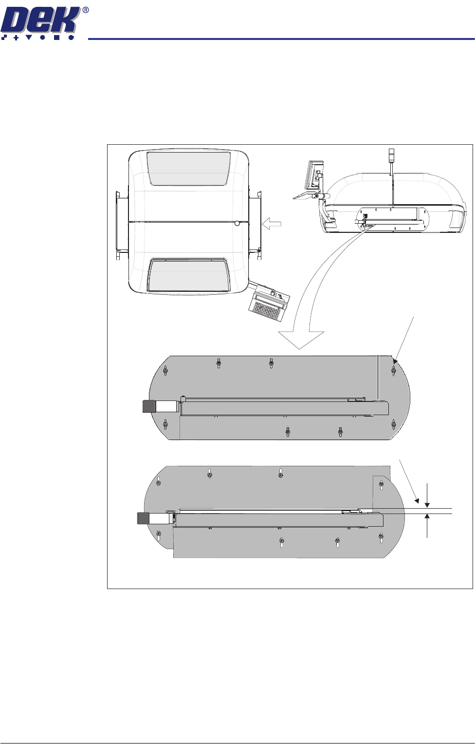
Safety Covers Where the High Throughput Conveyor (HTC) option is used, the transport rails
extend out beyond the normal machine footprint. Special safety covers have
been provided in place of the standard safety covers (see also the SGC Type
iX version.)
Figure 3-10 HTC Safety Covers
The covers are fitted to the side panels to protect personnel from inadvertent
access to the board entry/exit ports.
A pair of HTC safety covers are mounted on both the left and right hand sides
of the printer. The covers have slotted holes on the two cover halves allowing
the user to set sufficient gap for the product to be moved into and out of the
printer without restriction, while still protecting the operator from potential harm.
To remove the safety cover, remove the safety cover securing screws.
View on Arrow A
(top part of machine)
Gap Adjustment Slots
Set Gap > Product Thickness
HTC
(showing the two halves)
Safety Covers
A

COVERS
MACHINE COVERS
3.28 Technical Reference Manual Chapter Issue 2 Sep 09