Covers.pdf - 第7页
COVERS MACHINE COVERS Chapter Issue 2 Sep 09 Technical Reference Manu al 3.7 Rear Corner Panels T o remove the rear corner p anels, carry out the following: 1. Remove the corresponding upper side panel (as det ailed prev…
COVERS
MACHINE COVERS
3.6 Technical Reference Manual Chapter Issue 2 Sep 09
7. Remove the switch release tool from the contact assembly.
NOTE
To refit the contact assembly to the switch body, using the locating keyway,
push the two units together until they click into place.
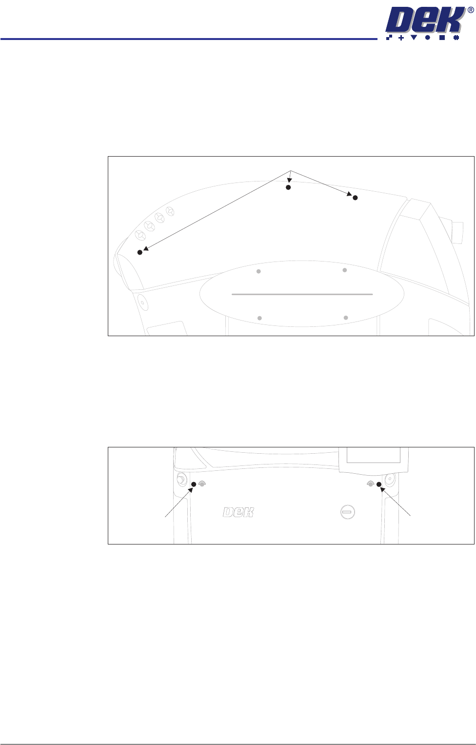
8. Release the three quarter-turn fasteners that secure the upper side panel
and remove the panel.
9. Repeat Steps 3 to 8 for the other side panel, if required.
Front Corner Panels To remove the front corner panels, carry out the following:
1. Remove the front panel.
2. Remove the corresponding upper side panel (as detailed previously).
3. Release the quarter-turn fastener that secures the corner panel.
4. Lift the corner panel upwards to disconnect the panel from the side panel
and the guide pins that locate the panel to the machine frame.
5. Repeat Steps 2 to 4 for the other corner panel, if required.
Upper Side Panel Quarter-Turn Fasteners
Front Corner
Panel Quarter-
Turn Fastener
Front Corner
Panel Quarter-
Turn Fastener
COVERS
MACHINE COVERS
Chapter Issue 2 Sep 09 Technical Reference Manual 3.7
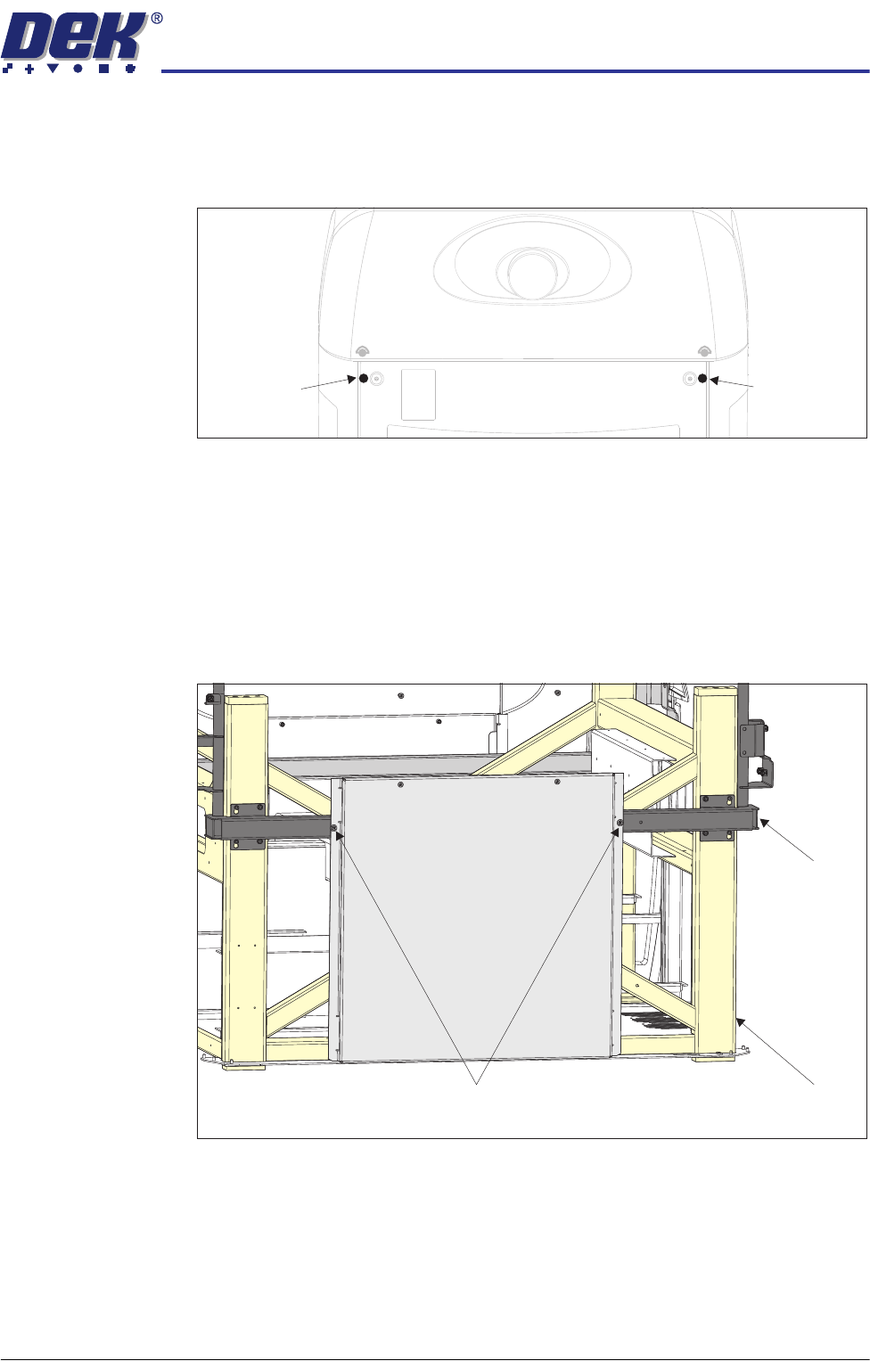
Rear Corner Panels To remove the rear corner panels, carry out the following:
1. Remove the corresponding upper side panel (as detailed previously).
2. Release the quarter-turn fastener that secures the corner panel.
3. Lift the corner panel upwards to disconnect the panel from the side panel
and the guide pins that locate the panel to the machine frame.
4. Repeat Steps 1 to 3 for the other corner panel, if required.
Side Panels To remove the side panels, carry out the following:
1. Remove both corresponding corner panels (as detailed previously).
2. Using a cross head screwdriver, release the two fasteners that secure the
side panel to the cover frame.
3. Lift the side panel upwards to clear the two guide pins that locate the panel
to the machine frame.
Rear Corner
Panel Quarter-
Turn Fastener
Rear Corner
Panel Quarter-
Turn Fastener
Side Panel Securing Fasteners
View on Right Hand Side of Machine
Cover Frame
Main Frame
COVERS
MACHINE COVERS
3.8 Technical Reference Manual Chapter Issue 2 Sep 09
Sliding Glass
Cover Machine
Type iX
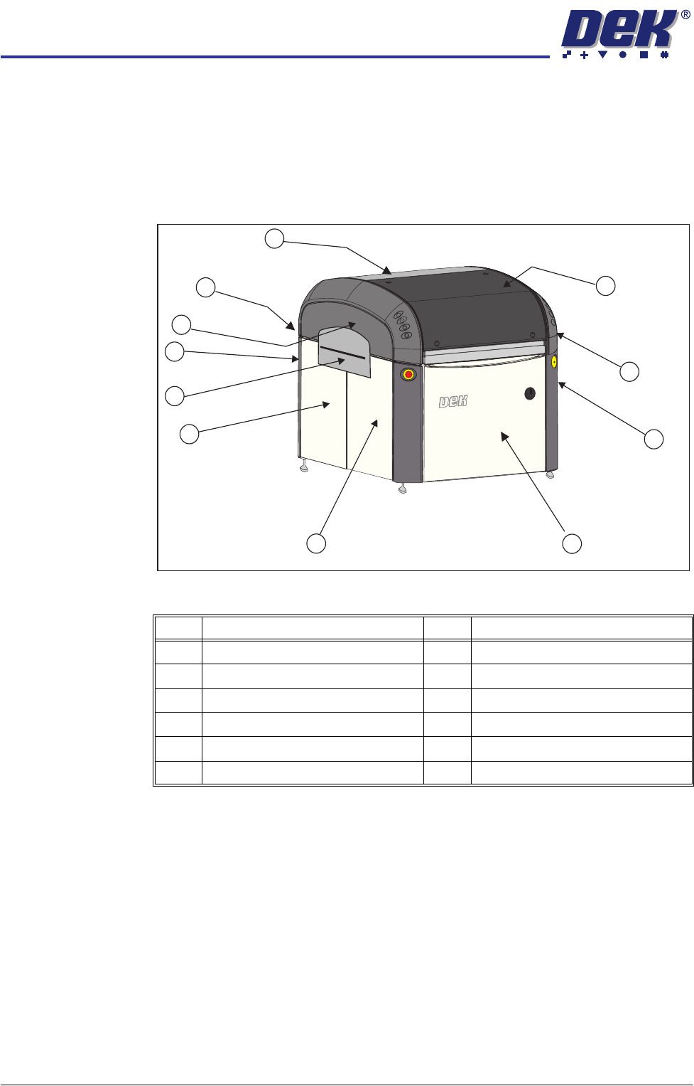
In order to protect personnel and prevent damage to the machine, ten covers
are fitted to the machine.
The sliding glass cover, the rear printhead cover and two upper side panels
which house the control switches protect the upper part of the machine. The
four corner panels, front and rear panels, safety covers and the front and rear
side panels protect the lower part of the machine.
Figure 3-4 Sliding Glass Cover Type iX
NOTE
Some of the covers can only be removed in a specific order due to the covers
interlocking with each other.
Item Description Item Description
1 Sliding Glass Cover 7 Safety Cover (2 positions)
2 Right Hand Upper Side Panel 8 Rear Corner Panel (2 positions)
3 Front Corner Panel (2 positions) 9 Left Hand Upper Side Panel
4 Front Panel 10 Rear Panel
5 Front Side Panel (2 positions) 11 Rear Printhead Cover
6 Rear Side Panel (2 positions)
1
2
3
4
5
6
9
11
10
8
Front Left Quarter View
7