88226673-01-03 Technical Reference Manual - (Production Iss 03 November 2020).pdf - 第4页
Issue 03 November 2020 Safety Warning Notices To ensure the safe operation of equipment , all perso nnel must follow generally accepted safety procedures. These procedures ensure their own safety and the safety of thos e…

Issue 03 November 2020
Table of Contents
SAFETY...................................................................................................................................................... 3
WARNING NOTICES ........................................................................................................................................................ 4
INSTALLATION .......................................................................................................................................... 5
TECHNICAL DATA ............................................................................................................................................................ 6
TRANSPORTATION .......................................................................................................................................................... 7
INDICATOR BEACON ..................................................................................................................................................... 10
OPERATION.............................................................................................................................................. 11
INITIALIZING THE MACHINE ......................................................................................................................................... 11
DISCONNECT AND SHUTDOWN PERIODS ................................................................................................................ 15
TEMPERATURE DISPLAY – THE TEMPERATURE DISPLAY ON THE PRINTER MMI SHOULD READ THE
SAME AS THE TEMPERATURE DISPLAYED ON THE PID CONTROLLER. IF THIS IS NOT THE CASE
VR1 CAN BE ADJUSTED SO THAT BOTH DISPLAYS READ THE SAME. SEE FIG19 ............................. 16
PREVENTATIVE MAINTENANCE ............................................................................................................. 17
SCHEDULED MAINTENANCE ....................................................................................................................................... 18
BEACON/PCB INTERPRETATION AND FAULT ANALYSIS ...................................................................................... 19
BEACON AND PCB INTERPRETATION ...................................................................................................................... 19
DISPLAY AND CONDENSATE ERROR CHECKLIST .................................................................................................. 23
ELECTRICAL FAULTS .................................................................................................................................................... 24
DIAGNOSTIC FLOW CHARTS .................................................................................................................. 24
Issue 03 November 2020
Safety
Warning Notices
To ensure the safe operation of equipment, all personnel must follow generally accepted
safety procedures. These procedures ensure their own safety and the safety of those
around them. In this manual and on the machine, safety symbols of the type described
below are shown when a potential hazard is given, the advisory notices should be
heeded at all times.
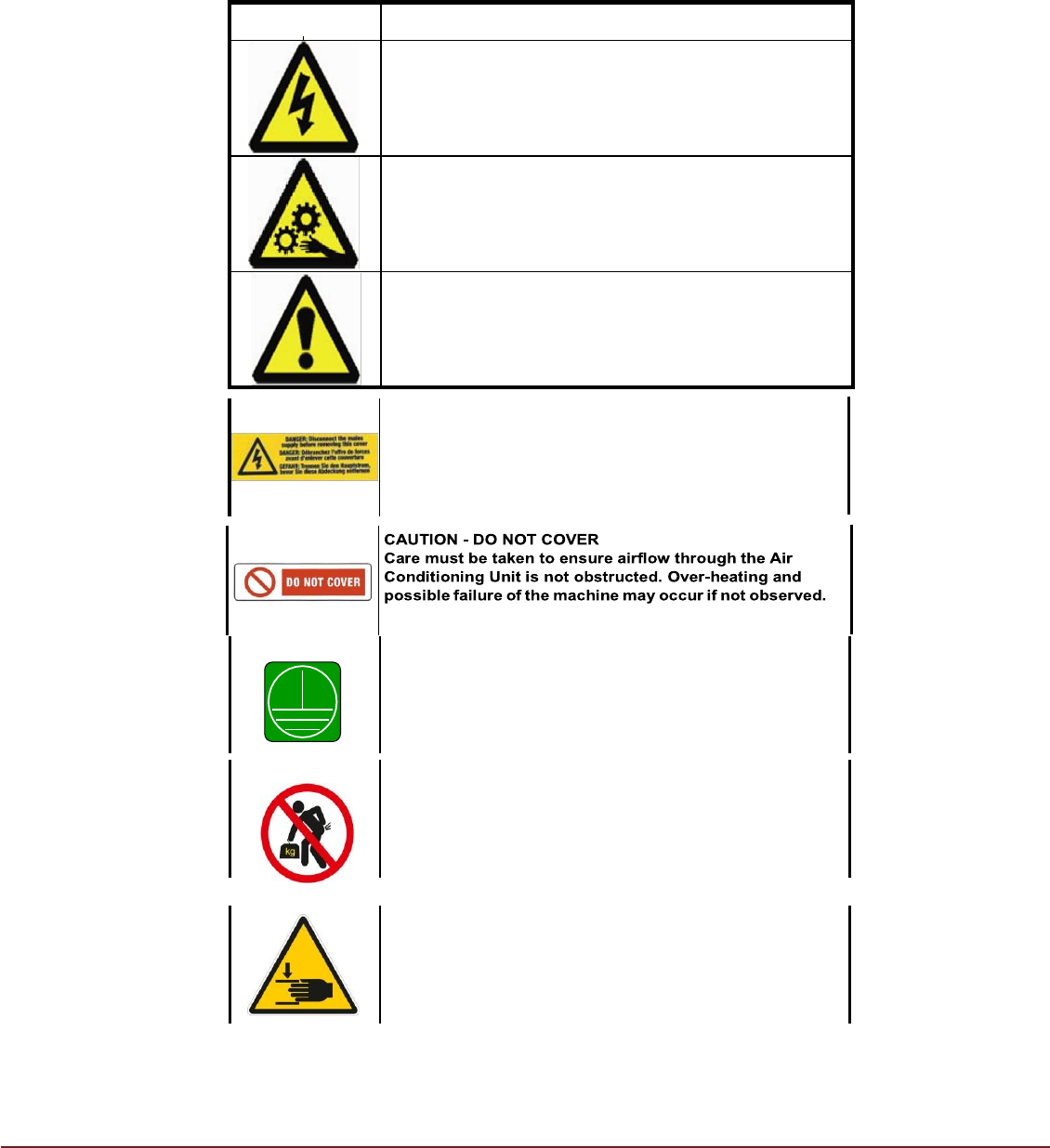
SYMBOL
DEFINITION
WARNING
ELECTRICAL HAZARD. High electrical voltage is present
that could cause injury or death. Do not remove protective
covers from the equipment housings or override protective
devices.
WARNING
BEWARE OF MOVING PARTS. Rotating fans are present that
could cause injury or death. Switch off power to fan motors
before removing panels and proceed with caution.
CAUTION
Refers to a possibly harmful situation. If not avoided,
damage could be caused to the product or something in its
environment.
WARNING - DANGER
Ensure machine is isolated from all sources of electrical
energy before removing access covers for service and
maintenance.
PROTECTIVE EARTH CONNECTION
If it is necessary to remove Protective Earth Connections to
enable repair/maintenance, care should be taken to ensure
connections are remade on completion and prior to
reinstating the machine power supply.
NO MANUAL LIFT
This appliance will require mechanical assistance when
lifted.
FINGER TRAP RISK
There is a risk of trapping fingers when installing the unit.

Issue 03 November 2020
Intended Use
The Top Mount Temperature Control Module (TM TCM) is a precision temperature
control module designed to enhance the Print Process by providing a highly stable and
accurately controlled air temperature within ASM’s range of printers.
The operating range of the TM TCM offers wide control of the process temperature either
side of factory ambient. As applications become more varied the requirement to produce
high yield results can be aided by the ability to heat as well as cool from factory ambient.
The TM TCM uses a re-circulating air system. Air entering the TM TCM is passed via a
fan through an air conditioning module where it is cooled and dehumidified before being
ducted into a plenum containing air heaters. A PID controller modulates the power output
of the heaters to accurately achieve the required set temperature. The temperature
conditioned air is ducted into the print process area of the ASM printer. The air is then re-
circulated back to the TCM via vents located on the underside of the TM TCM. An air
deflector has designed to achieve minimal airflow rates over the process area prolonging
tack performance of solder pastes and increasing stencil life.
Due to its optimized design and re-circulating system, the TM TCM is energy efficient
and requires minimal input power from a single-phase mains supply. The TCM will
automatically shut down following a predetermined delay if the printer is powered down
or when the printer covers are left open. The design minimises the production of waste
heat, which is vented through the top of the TM TCM alleviating the need for any
connection to factory extraction systems.
To monitor process temperature the TM TCM utilizes the output from the printer’s
integrated Temperature Sensor located on the print carriage. This results in accurate
feedback and control with the option to SPC log the print process temperature.
The possibility of process contamination is reduced due to the TCM maintaining a higher
air pressure within the printer compared to the surrounding environment thus limiting the
ingress of airborne particles.
The Module’s operating status is indicated by provision of a 'four colour' beacon clearly
visible to line operators. Any condensate produced can be gravity piped to drain or
collected in an easy to empty container. Two stage sensor monitors condensate level
and will give a warning via the beacon when the container requires emptying. The TCM
will automatically shut down if the container is not emptied to prevent overflow.
The TCM has been designed for robust reliable operation, resulting in a long lifetime
product. Ergonomic modular design features allow for ease of maintenance without any
requirement for specialist refrigeration resource.
WARNING – Use only as described.
Consult manufacturer before using for any other purpose.