00196376-0102_UM S-Feeder_EN.pdf - 第19页
General Linear Vibratory Feeder, Typ e 3 Technical D ata User Manual SIPLACE S-Feeder 19 1.3.3 Linear Vibratory Feeder, Type 3 Operating the feeder For processing componen ts in stick magazines. Item number: 00142031-xx …
General
Technical Data Bulkcase Feeders
18 User Manual SIPLACE S-Feeder
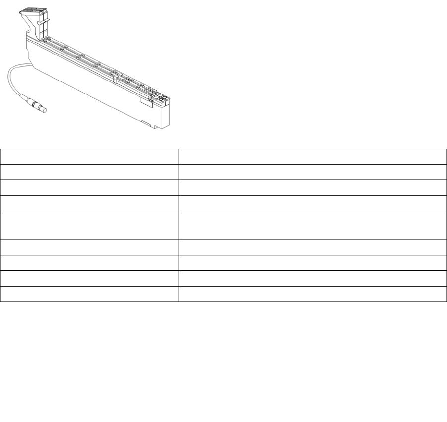
1.3.2 Bulkcase Feeders
Operating the feeder
Bulk goods feeder – for processing SMD components from
the Murata bulkcase cassette (DIN IEC 286/6)
Item number: 00142318-xx
Feeder width: 30.6 mm
Component spectrum: 0402, 0603, 0805, Mini-Melf, Micro-Melf
No. tracks: 2
No. of occupied locations on changeo-
ver table:
1
Tape material: Murata cassette
Pickup positions: 1
Feeder time (cycle time): < 60 ms
Changeover time: ≤ 15 seconds
Machine: All placement machines in the SIPLACE family
(except HS-180 / SP-120, MS-1xx, MS-72/90 and X4i)
Station software: From version 8.006
Line computer UNIX soft-
ware:
From version 401.002
SIPLACE Pro: From version 1.3
General
Linear Vibratory Feeder, Type 3 Technical Data
User Manual SIPLACE S-Feeder 19
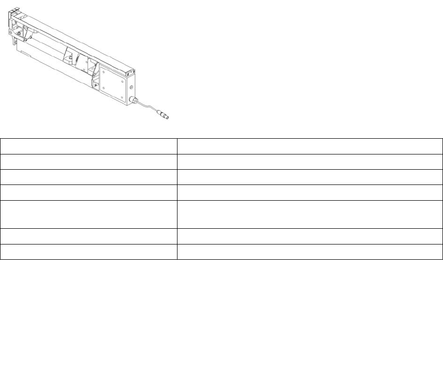
1.3.3 Linear Vibratory Feeder, Type 3
Operating the feeder
For processing components in stick magazines.
Item number: 00142031-xx
Feeder width: 28 mm
Component spectrum: Components in stick magazines
No. tracks: 1, 2 or 3, depending on stick magazine used
No. of occupied locations on changeo-
ver table:
1
Pickup positions: 1
Vibration time: Can be set from 400 to > 1000 ms
Machine: All machines in the SIPLACE family (except X4i)
Station software: All versions
Line computer UNIX soft-
ware:
All versions
SIPLACE Pro: From version 1.3
General
Installing the Feeders Dip Modules
20 User Manual SIPLACE S-Feeder
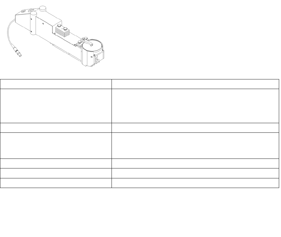
1.3.4 Dip Modules
Operating the feeder
1.4 Installing the Feeders
A general description of how to install the feeders is provided in the operating manuals of the respective
placement machines.
For processing with conductive adhesive, which is applied to
the components during placement.
Item number: 00117010-xx
Processable component sizes:
On IC head
On 6 segment RV head
(old manual)
max. 36x36 mm
max. 13x13 mm
Location required on changeover table: 3x two 8 mm tracks
Possible locations: Track 7 to track 111
(track 7 and track 111 = center of DIP module)
The DIP module can be set up max. 1x per machine.
Possible layer thickness to be set: 25 μm to 75 μm (in 10 μm steps)
max. tolerance of gap height: +/- 10 μm, delivery state +/- 5 mm
Materials for processing: Flux (paste) with high viscous flow or conductive adhesive
Machine: All machines in the SIPLACE family (except X4i)
Station software: 4xx, 5xx, 6xx
SIPLACE Pro: From version 3.0