00196376-0102_UM S-Feeder_EN.pdf - 第20页
General Installing the Feeders Dip Modules 20 User Manual SIPLACE S-Feeder 1.3.4 Dip Modules Operating the feeder 1.4 Installing the Feeders A general description of how to install the feeders is provided in the operatin…
General
Linear Vibratory Feeder, Type 3 Technical Data
User Manual SIPLACE S-Feeder 19
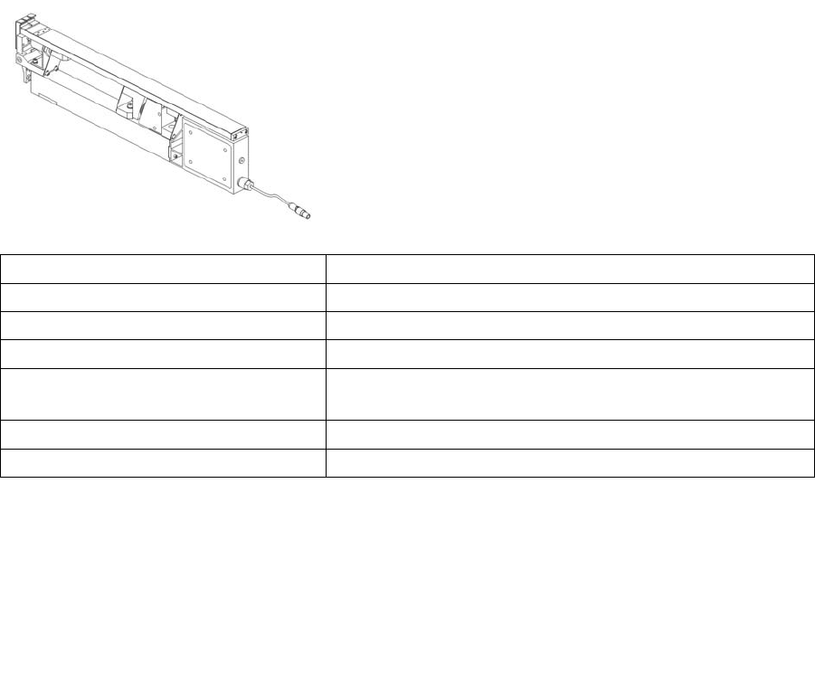
1.3.3 Linear Vibratory Feeder, Type 3
Operating the feeder
For processing components in stick magazines.
Item number: 00142031-xx
Feeder width: 28 mm
Component spectrum: Components in stick magazines
No. tracks: 1, 2 or 3, depending on stick magazine used
No. of occupied locations on changeo-
ver table:
1
Pickup positions: 1
Vibration time: Can be set from 400 to > 1000 ms
Machine: All machines in the SIPLACE family (except X4i)
Station software: All versions
Line computer UNIX soft-
ware:
All versions
SIPLACE Pro: From version 1.3
General
Installing the Feeders Dip Modules
20 User Manual SIPLACE S-Feeder
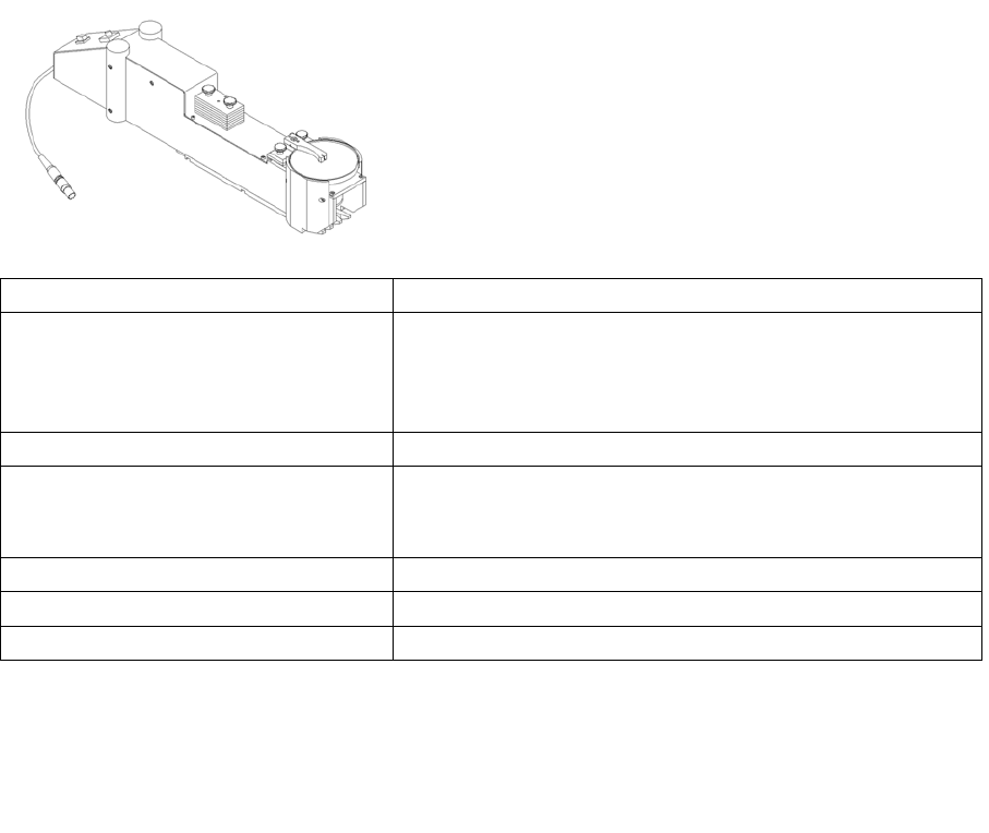
1.3.4 Dip Modules
Operating the feeder
1.4 Installing the Feeders
A general description of how to install the feeders is provided in the operating manuals of the respective
placement machines.
For processing with conductive adhesive, which is applied to
the components during placement.
Item number: 00117010-xx
Processable component sizes:
On IC head
On 6 segment RV head
(old manual)
max. 36x36 mm
max. 13x13 mm
Location required on changeover table: 3x two 8 mm tracks
Possible locations: Track 7 to track 111
(track 7 and track 111 = center of DIP module)
The DIP module can be set up max. 1x per machine.
Possible layer thickness to be set: 25 μm to 75 μm (in 10 μm steps)
max. tolerance of gap height: +/- 10 μm, delivery state +/- 5 mm
Materials for processing: Flux (paste) with high viscous flow or conductive adhesive
Machine: All machines in the SIPLACE family (except X4i)
Station software: 4xx, 5xx, 6xx
SIPLACE Pro: From version 3.0
General
Conventions for the Use of Hazard Symbols Safety Instructions
User Manual SIPLACE S-Feeder 21
1.5 Safety Instructions
1.5.1 Conventions for the Use of Hazard Symbols
This Operating Manual contains notes that must be observed to guarantee your personal safety and to
avoid damage to equipment. This information is marked by a warning triangle and is classified as follows:
1.5.2 Qualified Personnel
Qualified or adequately trained personnel means that these people are familiar with the setting up,
operation and maintenance of placement machines and add-on devices and are suitably qualified, e.g.
▪ Have been trained, instructed or authorized to switch on and off, isolate, earth and identify electrical
circuits and system components in accordance with normal safety standards.
▪ Have been trained or instructed in the upkeep and use of appropriate safety equipment in accord-
ance with normal safety standards.
▪ Have received first aid training.
1.5.3 Correct Usage
DANGER
as used in this Operating Manual means that fatal injuries, severe injuries or considerable
damage to equipment will occur, if this hazard note is not followed.
WARNING
as used in this Operating Manual means that fatal injuries, severe injuries or considerable
damage to equipment can occur, if this warning is not followed.
CAUTION
as used in this Operating Manual means that minor injuries or damage to equipment may occur
if this caution note is not followed.
NOTICE
as used in this Operating Manual provides information about the product or indicates a part of
the Operating Manual that requires particular attention.
WARNING
Type and source of the danger
The product may only be used for its intended purposes as described in the catalogs and tech-
nical descriptions and only with the third-party equipment and components recommended or
permitted by ASM Assembly Systems.
The proper and safe operation of the product requires correct transportation, storage, installa-
tion and assembly, plus careful, accurate utilization and servicing.