00196715-04_IM_SSW_704_03_SP1_DE_EN.pdf - 第45页
Station Software 704.03 SP1 / Installation Manual Ausgabe 10/2011 Edition 7.5 Checking/Updating the embedded software If the correct eSW versions are not available on the machine, the machi ne boot gets interrupted. ► In…
Station Software 704.03 SP1 / Installation Manual Ausgabe 10/2011 Edition
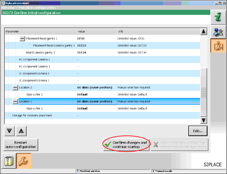
When you have selected all table configurations the following window is displayed, in which you
confirm the Auto-configuration.
Figure 7-8: Confirming Auto-configuration for SX1/SX2
► Click the Confirm changes and continue startup button to confirm the Auto-configuration.
7.3 SX+ placement machine
If the SX+ placement machine is to be used without gantries, this has to be configured in the Auto-
configuration after the machine has been booted. For this you have to select Ignore gantries at
the processing area in the machine configuration dialog.
7.4 SX4 placement machine
When the SX4 placement machine is booted for the first time you have to select the SX4 Flexible
entry for Machine frame manually in the Auto-configuration, if there are tables in outer position in
processing area 2, as this is not detected automatically via sensors. Tables in outer position are
used when stationary cameras are in use. Otherwise you select the SX4 High Speed entry.
44
Station Software 704.03 SP1 / Installation Manual Ausgabe 10/2011 Edition
7.5 Checking/Updating the embedded software
If the correct eSW versions are not available on the machine, the machine boot gets interrupted.
► In this case, perform an eSW download.
► Start an overall reference run for the machine.
7.6 Storage location of the machine files (calibration data etc.)
The machine-specific configuration, measurement and parameter data is stored in XML files under
C:\Sirio\Work\Individual. These XML files contain all the calibration data.
45
Station Software 704.03 SP1 / Installation Manual Ausgabe 10/2011 Edition
7.7 Necessary calibration steps
After upgrading from station software 701.xx and first booting of the station software, some
calibration steps are required.
Requirements:
– The eSW versions have been updated.
– The reference run has been successfully performed.
– A calibration nozzle (1235) has to be available on every C&P20A placement head at segment
1.
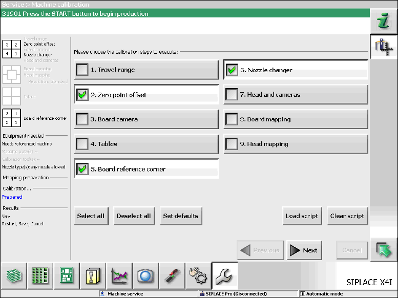
Figure 7-9: Required calibration steps
► Select the calibration steps that are highlighted in the figure and click on Next.
► Select all possible components in the following input masks (all conveyor lanes, all gantries, all
nozzle changers).
46