N7201A653E.pdf - 第203页
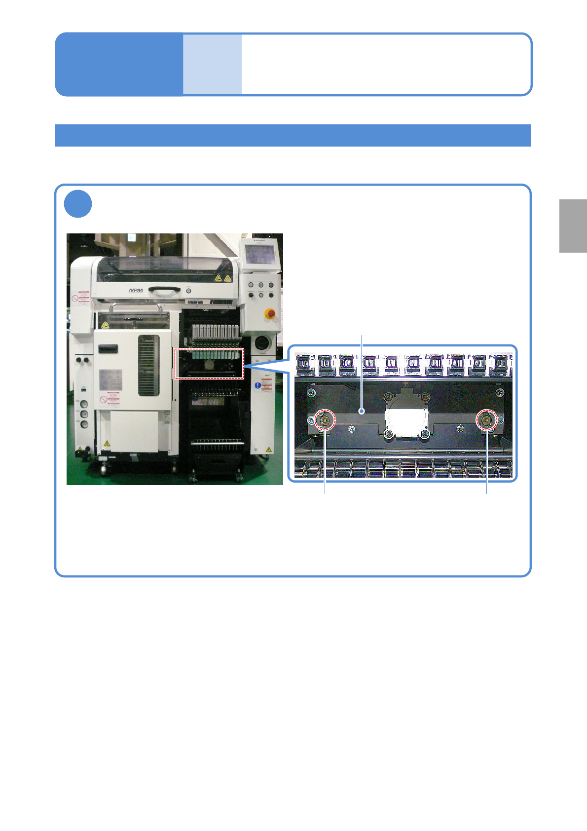
EJM1EJ-MB-06 M-02 NPM-TT2 6-17 -1 1 Apply grease to the guide block ● Apply grease to the guide block via the grease nipple. (two loc ations) (Use the grease gun. About 0.9cm 3 per pump) Grease: LCG100 Tool used : Grease…
EJM1EJ-MB-06M-02NPM-TT2
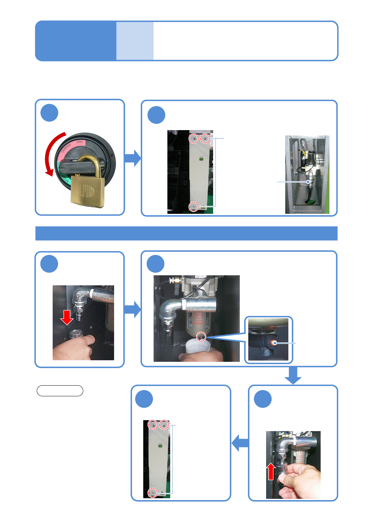
Inspecting the air drain
(regulator unit)
Describes how to inspect an air drain of the regulator unit.
Tool used: Lint free cloth, Allen wrench (2.5 mm) Time required: 5 minutes
2
Remove the lower-right cover located on the
rear of the machine to check for any water
accumulated in the air drain
●No water should accumulate in
the air drain under the
environmental conditions
specified by us.
NOTIICE
If water is accumulated in the air drain
3 4
Disconnect
the air hose
Drain the water out of the air drain
①Place a water-receiving bottle
(prepare on your own) under
the drain cock.
②Press the drain cock button to
drain water.
5
Connect the
air hose
●Wipe off any excess
moisture with a lint free cloth.
6
Close the lower-
right cover on the
rear of the machine
Air drain
Drain cock
button
6-16
●For machines operated under
environmental conditions other
than those specified by us,
periodically check the air drain
and drain water from it, if any.
Loosen the bolt
(using an Allen
wrench)
● Three locations
Tighten the bolt
(using an Allen
wrench)
●Three
locations
Maintenance
6-16
4
1
Turn OFF the
power and lock
the machine
OFF
EJM1EJ-MB-06M-02NPM-TT2
6-17-1
1
Apply grease to the guide block
●Apply grease to the guide block via the grease nipple. (two locations)
(Use the grease gun. About 0.9cm
3
per pump)
Grease: LCG100
Tool used: Grease gun Time required: 3 minutes
13-slot feeder unit
Grease nipple
Grease nipple
Guide block
Greasing the cutting
unit
Maintenance
6-17
Every
560
hours
PeriodicPeriodicPeriodicPeriodic
inspection
EJM1EJ-MB-06M-02NPM-TT2
6-18-1
Maintenance
6-18
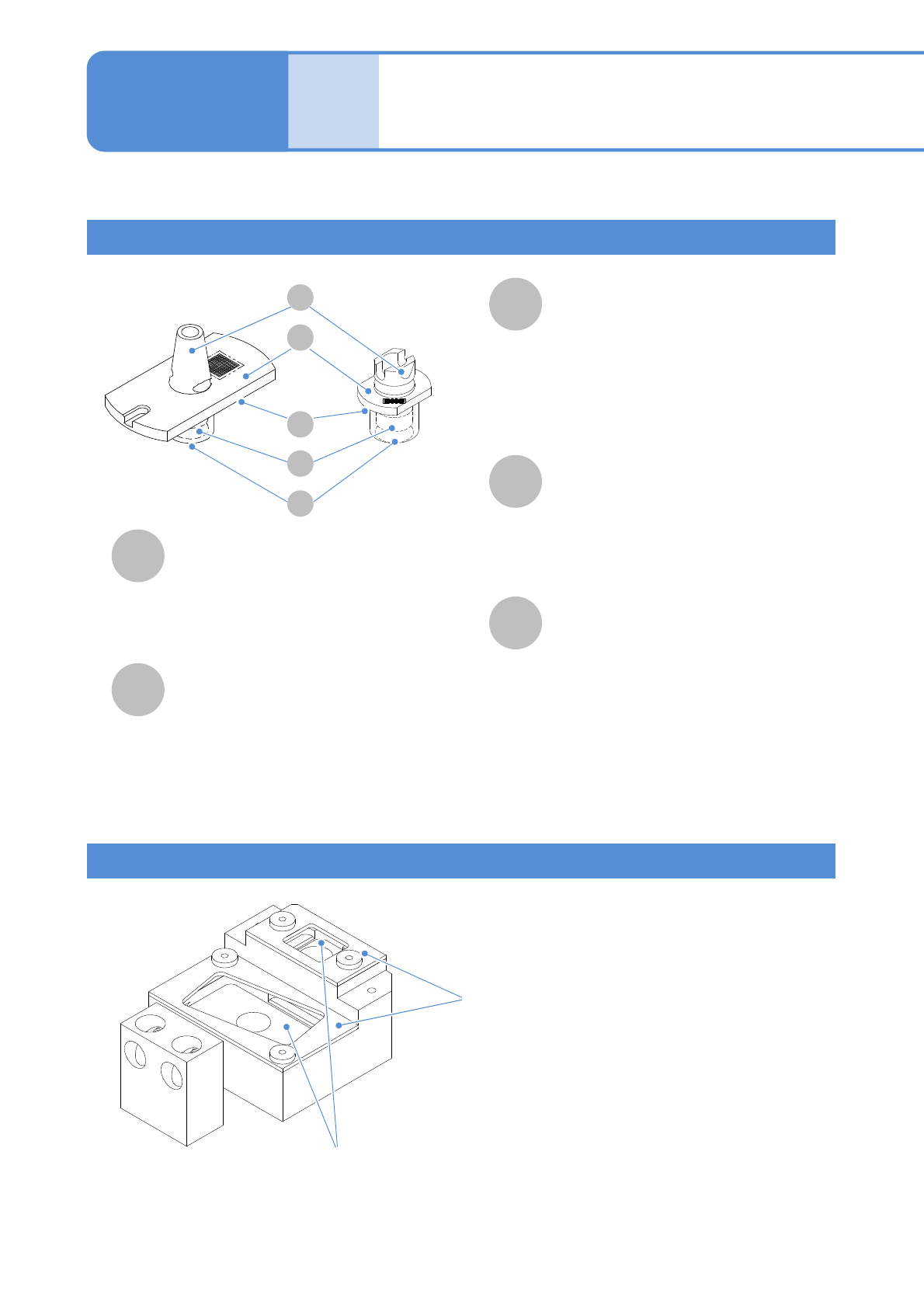
Name and role of a nozzle for support pins
A
B
D
E
C
Nozzle inside
(Foreign objects adhering inside the
nozzle hinder the pickup and
arrangement of the support pins, and
various detection functions using vacuum
pressure)
Nozzle changer for support pins
Describes how to clean the nozzle and nozzle changer for support pins.
The cleaning method is as same as the nozzle
for component pickup.
(→P.6-4)
(It is not necessary to use ultrasonic cleaning
equipment)
Nozzle flange upper surface
The nozzle type and serial No. are shown
by the 2D code. The 2D code area is
recognized by the head camera.
(Leaving this part dirty results in a
recognition error)
E
A
D
B
C
Nozzle changer upper cover
●When nozzles are manually removed, turn the
nozzle flange in a counterclockwise direction
until it is not stuck with the hole of the upper
cover and remove it upward.
Nozzle changer upper surface
(Any contamination of the nozzle changer
upper surface allows contaminants to adhere
to the nozzle reflector, resulting in
recognition errors)
Cleaning the nozzle (option) and
nozzle changer (option) for
support pins 1
Nozzle tip (nozzle section)
This is the part to directly contact with
the flange of the support pin, and it
picks support pins up.
(Contamination on the vacuum hole can
cause an pickup error)
●A vacuum pad is installed for stable
pickup.
Nozzle taper surface
This is the part to be chucked by the
nozzle holder of the placement head.
(Contamination on the taper surface and
chucking groove may cause an air leak
and faulty chucking)
Nozzle reflector
Unlike the nozzle reflector for component
placement, this is the same material as
flange. This part checks whether the
nozzle is properly placed or not by
reflecting the LED light from the multi-
recognition camera.
(Leaving this part dirty results in a
recognition error.)
This is the unit that is used to stock support pin
nozzles. When support pins are automatically
changed upon changeover, the placement head
automatically changes nozzles.