00192801-01.pdf - 第34页
2 Safety User M anual V 1.15 - P roductivity Lift 2.8 Indicator lamps Software version V 40. 1 1 Edition 01/2001 26
User Manual V 1.15 - Productivity Lift 2 Safety
Software version V 40.11 Edition 01/2001 2.7 Emergency stopping switches
25
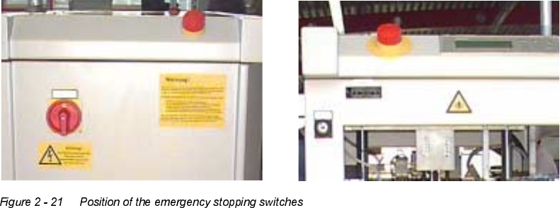
(PHUJHQF\VWRSSLQJVZLWFKHV
There are two emergency stopping switches on each lift module. One is located on the side of the
control desk and the other on the rear side of the lift.
,QGLFDWRUODPSV
The device is equipped with one green and one white indicator lamp. The lamps have the following
functions assigned to them:
Green - illuminated: system in automatic operating mode.
White - illuminated : system fault.
2 Safety User Manual V 1.15 - Productivity Lift
2.8 Indicator lamps Software version V 40.11 Edition 01/2001
26

User Manual V 1.15 - Productivity Lift 3 Assembling and installing
Software version V 40.11 Edition 01/2001 3.1 Power supply 230V/50Hz or 110V/60Hz
27
$VVHPEOLQJDQGLQVWDOOLQJ
:$51,1*
Work on a system that is not (yet) properly service engineers from the manufacturing company
may only carry out set up.
127(
For assembling and maintenance refer to the existing Installation and Maintenance Manual.
3RZHUVXSSO\9+]RU9+]
The machines can be operated using two different power supplies. By changing the wiring of the
power supply PSU 500L24 the appropriate power setting can be adjusted. Please refer to the cir-
cuit diagrams.
,QVWDOODWLRQDQGRSHUDWLRQLQVWUXFWLRQV
For the installation and operation of the productivity lift the following advises have to be observed:
1. Area load allowed for undercover 0,2 t/m²
2. Room temperature 15°C to 35°C
3. Humidity in the area 30% to 70%
4. Average humidity ≥ 45%