00192801-01.pdf - 第63页
User Manual V 1.15 - Productivity Lift 6 Set-up mode Software version V 40.1 1 Edition 01/2001 6.3 Ramp up mode / Ramp down mode 55 5DP SXSPRG H5D PSGRZ QP RGH ([DPSO HRI&OXV WHUZL WKWK UHH6LSOD…
6 Set-up mode User Manual V 1.15 - Productivity Lift
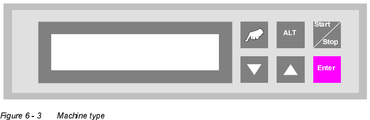
6.2 Machine type Software version V 40.11 Edition 01/2001
54
Convert 4 → 2 : Convert module from 4 tracks to 2 tracks, whereby 4 tracks indicate the lower
and upper two tracks.
$SSOLFDWLRQ
A suitable device should be used to break up a long placement line to allow
access for people, for example. This reduces the transport tracks to 2 tracks,
since a device can not have two tracks on the lower transport level. With the
convert module 4→2, PCB transport is reduced to 2 tracks, separated ac-
cording to assembled and unassembled PCBs.
Convert 2 → 4 : Convert module from 4 tracks to 2 tracks, whereby 4 tracks indicate the lower
and upper two tracks.
$SSOLFDWLRQ
A suitable device should be used to break up a long placement line to allow
access for people, for example. This reduces the transport tracks to 2 tracks,
since a device can not have two tracks on the lower transport level. With the
convert module 2→4, PCB transport is increased again to 4 tracks, sepa-
rated according to assembled and unassembled PCBs, following this type of
interruption.
Output module : The final module is defined as the last lift in the direction of transit, after the
Siplace systems. Essentially, the final module has no lower belt. If the lift is
implemented as the final module, the above mentioned system types can not
be selected. The PCBs are transferred from tracks 1, 2 and 4. Transfer to
tracks 1 and 2 has priority. The printed circuit boards can only be delivered
at the final module via outlet tracks 1 and 2. No PCBs can be transferred from
track 3 or transported further on this track.
Machine type
Input module
User Manual V 1.15 - Productivity Lift 6 Set-up mode
Software version V 40.11 Edition 01/2001 6.3 Ramp up mode / Ramp down mode
55
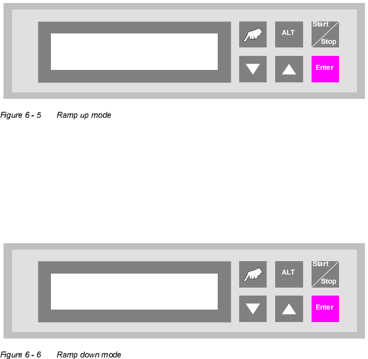
5DPSXSPRGH5DPSGRZQPRGH
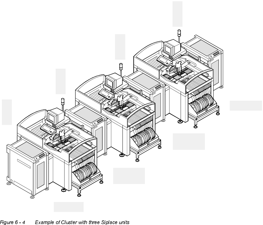
([DPSOHRI&OXVWHUZLWKWKUHH6LSODFHXQLWV
E
i
n
g
a
n
g
s
m
o
d
u
l
I
n
p
u
t
m
o
d
u
l
e
Belademodus 1:2
Ramp up mode 1:2
Z
w
i
s
c
h
e
n
m
o
d
u
l
C
l
u
s
t
e
r
m
o
d
u
l
e
Z
w
i
s
c
h
e
n
m
o
d
u
l
C
l
u
s
t
e
r
m
o
d
u
l
e
E
n
d
m
o
d
u
l
O
u
t
p
u
t
m
o
d
u
l
e
Belademodus 1:1
Entlademodus 1:0
Ramp up mode 1:1
Ramp down mode 1:0
Belademodus 1:0
Entlademodus 1:1
Ramp up mode 1:0
Ramp down mode 1:1
Entlademodus 1:2
Ramp down mode 1:2
6 Set-up mode User Manual V 1.15 - Productivity Lift
6.3 Ramp up mode / Ramp down mode Software version V 40.11 Edition 01/2001
56
5DPSXSPRGH
PCB distribution parameter, which defines the loading sequence of the PCBs within a cluster of
Siplace units. The value of x depends on the number of Siplace units within a cluster.
The menu allows to set the value x between 0...9.
5DPSGRZQPRGH
PCB distribution parameter, which defines the unloading of the PCBs within a cluster of Siplace
units. The value of x depends on the number of Siplace units within a cluster.
The menu allows to set the value x between 0...9.
Ramp up mode
1 to x
Ramp down mode
1 to x