00192801-01.pdf - 第51页
User Manual V 1.15 - Productivity Lift 5 Configuration Software version V 40. 1 1 Edition 01/2001 5.15 Reference width 1 43 $GGUHVVZ LG WK 5HIHU HQFHZ LG WK This setting d efines the re ference width …
5 Configuration User Manual V 1.15 - Productivity Lift
5.14 Address width 1 / Address width 2 - Option Software version V 40.11 Edition 01/2001
42
$GGUHVVZLGWK$GGUHVVZLGWK2SWLRQ
This function is optional. It allows an automatic width adjustment of the Productivity Lifts within a
line configuration. This menu is not active, if this option is available and "Width adjusting 1" and
"Width adjusting 2" (chapter 5.11 and 5.12) has been set to "manual".
The width setting of the Siplace Placement units is mandatory for the width setting of the Produc-
tivity Lifts. To enable the automatic width setting, there are certain line configuration settings re-
quired. It is required, that there is a CAN-BUS featured module in front of the input module and a
Siplace placement unit behind the output module. The Siplace unit must be followed by a CAN-
BUS featured module.
The module before the input module (n-1) has address 1. This address is used to verify the width.
The module after the last placement machine (n+1) owns address 2. The requested data from this
module are used to set the width. The width of the Productivity Lifts in such a line is changed only
when all Siplace Placement units between input and output module carry no PCB. The module
(n+1) detects the new width setting at the last placement unit, using a sensor. The new width set-
ting is transmitted via CAN-BUS to the Productivity Lifts in the line.
Other settings are also possible e.g. module with address 1 is also addressed as module 2. With
this setting module (n-1) is used to verify and to transmit the width setting to the other Productivity
lifts.
The set up for this option must be performed by a qualified Service engineer.
127(
This setting has to be conducted by a Service engineer of the equipment manufacturer or needs
to be approved by Service engineer of the equipment manufacturer!
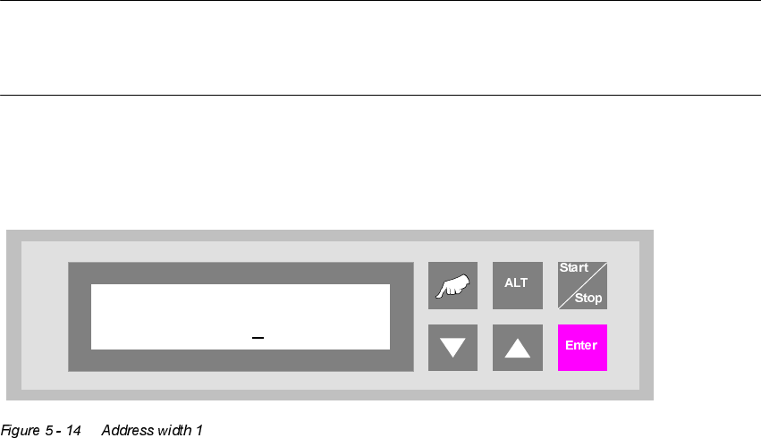
$GGUHVVZLGWK
Address width 1
0000
User Manual V 1.15 - Productivity Lift 5 Configuration
Software version V 40.11 Edition 01/2001 5.15 Reference width 1
43
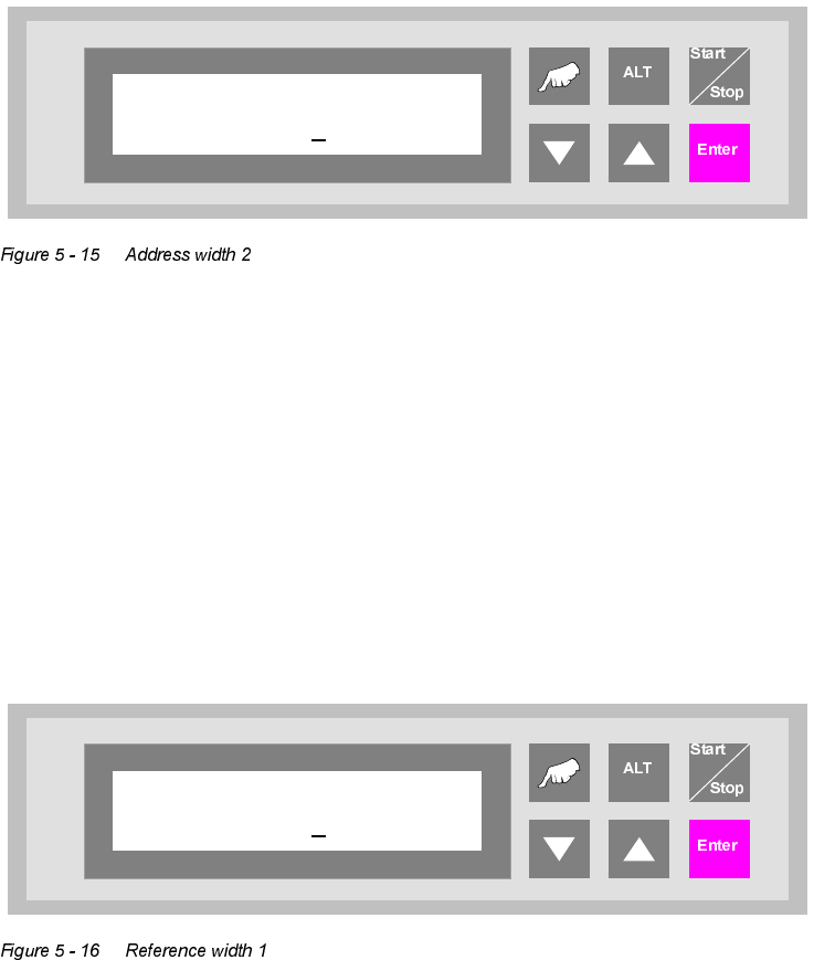
$GGUHVVZLGWK
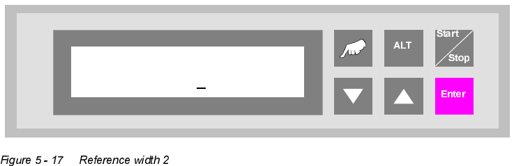
5HIHUHQFHZLGWK
This setting defines the reference width of the Top Conveyor (only option). This setting allows the
matching of displayed width and actual width of the Top Conveyor transport. By changing the set-
ting the width is increased or decreased. A typical value is between 0480 - 0490.
This menu item is only available, if the function "Width adjusting 1" is activated (chapter 5.11). The
standard configuration is not equipped with an automatic width setting of the Top Conveyor.
The lowest increment is [0.1mm].
Address width 2
0000
Reference width 1
0480
5 Configuration User Manual V 1.15 - Productivity Lift
5.16 Reference width 2 Software version V 40.11 Edition 01/2001
44
5HIHUHQFHZLGWK
This setting defines the reference width of the Shuttle Conveyor. This setting allows the matching
of displayed width and actual width of the Shuttle Conveyor. By changing the setting the width is
increased or decreased. A typical value is between 0480 - 0490.
This menu item is only available, if the function "Width adjusting 2" is activated (chapter 5.12). The
standard configuration is equipped with an automatic width setting of the Shuttle Conveyor.
The unit of value is [0.1mm].
Reference width 2
0480