00900330-01_UM_ASM-ProcessLens_EN.pdf - 第39页
2 Safety 2.5 Safety features Instruction manual ASM ProcessLens 03/2021 39 Fig.31: Position of protective switches on the machine 1 Front protective hood 2 Protective cover switch Protective cover switch (see 2.5.2.3 &q…

2 Safety
2.5 Safety features
38 Instruction manual ASM ProcessLens 03/2021
Key switch ON/OFF
(see 2.5.2.1 "Position of switches and buttons on the machine" [}36])
Turn on the control power manually and switch the conveyor into pass through mode when the PC
is down.
► Close the GUI program.
► Switch off the machine by the main switch.
► Wait for 30 sec and then switch on the machine at the main switch.
► Turn the key switch to the left and release to turn on the control power.
► Turn the key switch to the right.
The conveyor set to pass through running mode.
External grounding point
(see 2.5.2.1 "Position of switches and buttons on the machine" [}36])
Always ensure that people, the workplace and packaging are safely earthed when handling electro-
static sensitive components. Please observe chapter 2.8 ESD guidelines.
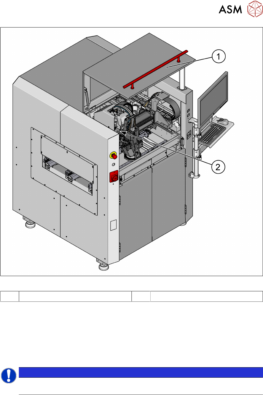
2.5.2.3 Position of protective switch on the machine
Unexpected starting of the machine is prevented by the protective cover switch.
2 Safety
2.5 Safety features
Instruction manual ASM ProcessLens 03/2021 39
Fig.31: Position of protective switches on the machine
1 Front protective hood 2 Protective cover switch
Protective cover switch
(see 2.5.2.3 "Position of protective switch on the machine" [}38])
This protective cover switch check whether the protective hood is closed. When it‘s closed, the
safety interlock module is closed. The protective hood cannot be opened (it is locked) unless the
user actively presses the software button "Open front door" from the ASM SPI GUI inspection soft-
ware. If the cover is opened, the safety interlock module will open. Individual components are dis-
abled or remain enabled.
NOTICE
ASM ProcessLens electrical diagrams
For details, please refer to the ASM ProcessLens electrical diagrams.
2 Safety
2.6 Residual voltages and discharge times in the machine
40 Instruction manual ASM ProcessLens 03/2021
2.5.3 Emergency stop loops and signaling circuit
2.5.3.1 Emergency stop loop structure
The following contacts are connected in series and form the emergency stop loop:
●
Make contact elements for the protective cover switch
●
Make contact elements for the emergency stop button
All the signaling contacts are closed when the machine is on standby. If a protective cover, for
example, is raised, the associated signaling contact opens and the safety interlock module re-
leased.
2.5.3.2 Description of the functions of the EMERGENCY STOP loops
The following conditions must be fulfilled in order to start and operate the machine:
●
The protective hood must be closed.
●
The emergency stop button must be released.
The machine is then ready for use.
2.6 Residual voltages and discharge times in the machine
2.6.1 Energy state of the machine after the EMERGENCY STOP button is pressed
If the EMERGENCY STOP button is pressed, the voltage are reduced to harmless residual
voltages in a very short time.
WARNING
Some parts of the system carry potentially lethal voltages
The machine is supplied with 1/N/PE ~ 240, 50/60 Hz mains voltage. This means that some
parts of the system carry potentially lethal voltages - even when switched off at the main
power switch. Incorrect handling of the machine can therefore result in death or severe in-
jury or considerable damage to equipment.
► Always follow the applicable accident prevention and safety regulations (particularly
DIN EN 60204, part 1 or IEC 60204, part 1) and the safety regulations in your own
country.
► The covers over the power supply unit may ONLY be opened by appropriately quali-
fied and trained personnel.
NOTICE
ASM ProcessLens electrical diagrams
For details, please refer to the ASM ProcessLens electrical diagrams.
2.6.2 Energy state of the machine after switching off the main power switch
WARNING
Some parts of the system carry potentially lethal voltages
The machine is supplied with 1/N/PE ~ 240, 50/60 Hz mains voltage. This means that some
parts of the system carry potentially lethal voltages - even when switched off at the main
power switch. Incorrect handling of the machine can therefore result in death or severe in-
jury or considerable damage to equipment.
► Always follow the applicable accident prevention and safety regulations (particularly
DIN EN 60204, part 1 or IEC 60204, part 1) and the safety regulations in your own
country.