00900330-01_UM_ASM-ProcessLens_EN.pdf - 第68页
4 Setting up and commissioning 4.3 Setting up the machine 68 Instruction manual ASM ProcessLens 03/2021 4.3.5.1 Presetting the height of the machine feet The machine stands on 4 feet. Fig.44: Presetting the height of th…
4 Setting up and commissioning
4.3 Setting up the machine
Instruction manual ASM ProcessLens 03/2021 67
4.3.4 Tools and equipment
You will need the following tools and equipment to adjust the height of your machine:
●
Open-ended wrench SW 19, SW 30, SW 36
●
One or two machine spirit level(s): accuracy 0.02 mm/m
●
Forklift truck (specification see 4.1.4.3).
4.3.5 Adjusting the machine height
The machine can be set at any PCB conveyor height within the following range:
●
900 mm ± 15 mm
●
930 mm ± 15 mm
●
950 mm ± 15 mm
CAUTION
Foot spacers
When using the 950 ± 15 mm PCB conveyor height, foot spacers are required to maintain
ASM ProcessLens measurement accuracy and stability.
NOTICE
PCB conveyor height
The PCB conveyor height is the distance between the top edge of the PCB conveyor belt
and the bottom edge of the machine feet.
4 Setting up and commissioning
4.3 Setting up the machine
68 Instruction manual ASM ProcessLens 03/2021
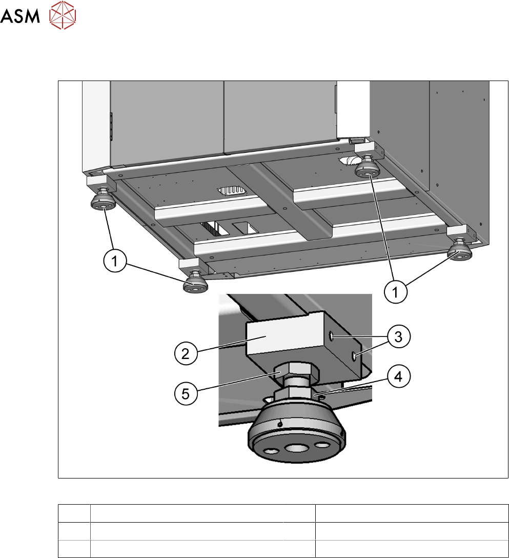
4.3.5.1 Presetting the height of the machine feet
The machine stands on 4 feet.
Fig.44: Presetting the height of the machine feet
1 Machine feet 2 Block for package and support
3 M10 x 20 for packaging 4 M24 x M36 nut
5 M24 x M36 nut
► Measure the approximate PCB conveyor height.
► Lift the ASM ProcessLens machine with a forklift.
► Loosen the two clamping nuts (4 and 5) with help of open end spanner size 36mm.
► Turn the ASM ProcessLens machine feet (1) with the bottom screw nut (4) so that the
machine reaches the desired PCB conveyor height.
► Repeat for the other three feet.
► Now use the forklift to carefully lower the machine until the machine feet touch the floor
evenly. There should always be a second person present to ensure that the machine remains
stable while it is being lowered.
See also
2 4.3.5.1 "Presetting the height of the machine feet" [}68]
4 Setting up and commissioning
4.3 Setting up the machine
Instruction manual ASM ProcessLens 03/2021 69
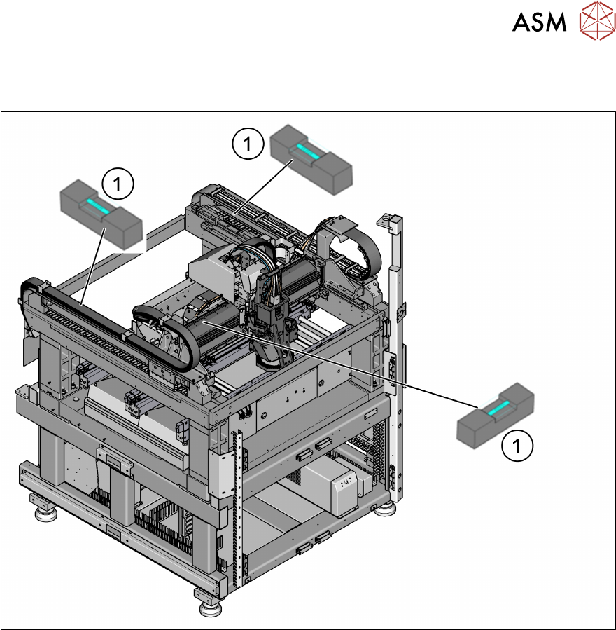
4.3.6 Levelling the machine
► Level the machine in the X and Y direction with the help of the machine spirit level.
Fig.45: Position of the machine spirit level in the X and Y direction
► Place the machine spirit levels (1) in the X and then the Y direction on the linear guide rails.
► Measure the distance between the upper edge of the PCB conveyor belt and the floor. This
distance should be the range to 950 mm, if the height of the machine is to be set to 950 mm.
Other heights also apply.
► Turn the bottom screw nut (item 4 in fig. "Presetting the height of the machine feet" [}68]) of
all four machine feet, so that the fluid in the machine spirit level does not deviate from its zero
point (tolerance within ±0.05mm) at the required conveyor height.
► Check the required board conveyor height.
► Once the machine has been levelled, tighten the top secure nut (item 3 in fig. "Presetting the
height of the machine feet" [}68]) to clamp all machine feet.
► Use the spirit level to check that the machine is precisely levelled (tolerance within
±0.05mm).
See also
2 4.3.5.1 "Presetting the height of the machine feet" [}68]