00900330-01_UM_ASM-ProcessLens_EN.pdf - 第51页
3 Machine description 3.1 Overview of the modules Instruction manual ASM ProcessLens 03/2021 51 1 Fixed clamped edge 2 Printed circuit board 3 Movable clamping device 4 Conveyor rail 5 +/- 4.5 mm PCB warpage in the direc…
3 Machine description
3.1 Overview of the modules
50 Instruction manual ASM ProcessLens 03/2021
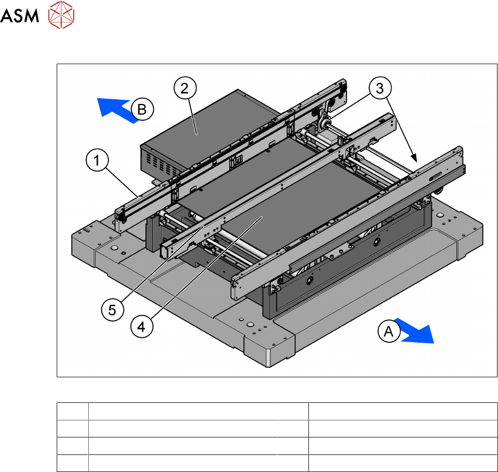
3.1.4 Single conveyor assembly
Fig.36: PCB single conveyor
A Front side of the machine B Rear side of the machine
1 Rear conveyor rail 2 Conveyor control unit
3 Fixed front rail 4 Lifting table
5 Stopper and sensors rail
3.1.4.1 Description
The PCB conveyor is a single lane conveyor. The machine requires a length of 1100 mm. Both
sides have a 150 mm extension to the upstream or downstream conveyor. The standard conveyor
is a front fixed rail and it only has one lifting table without input/output buffer. A conveyor extension
option exists to increase the length of the single stage conveyor to allow for a barcode capability to
be attached where no upstream conveyor exists.
The conveyor height can be selected on the machine to allow the machines to be integrated into
lines with a conveyor height of, 900, 930 or 950 mm. The standard height is 930 mm.
The communication between the PCB conveyors of the individual machines takes places via the
SMEMA or IPC-HERMES-9852 interface.
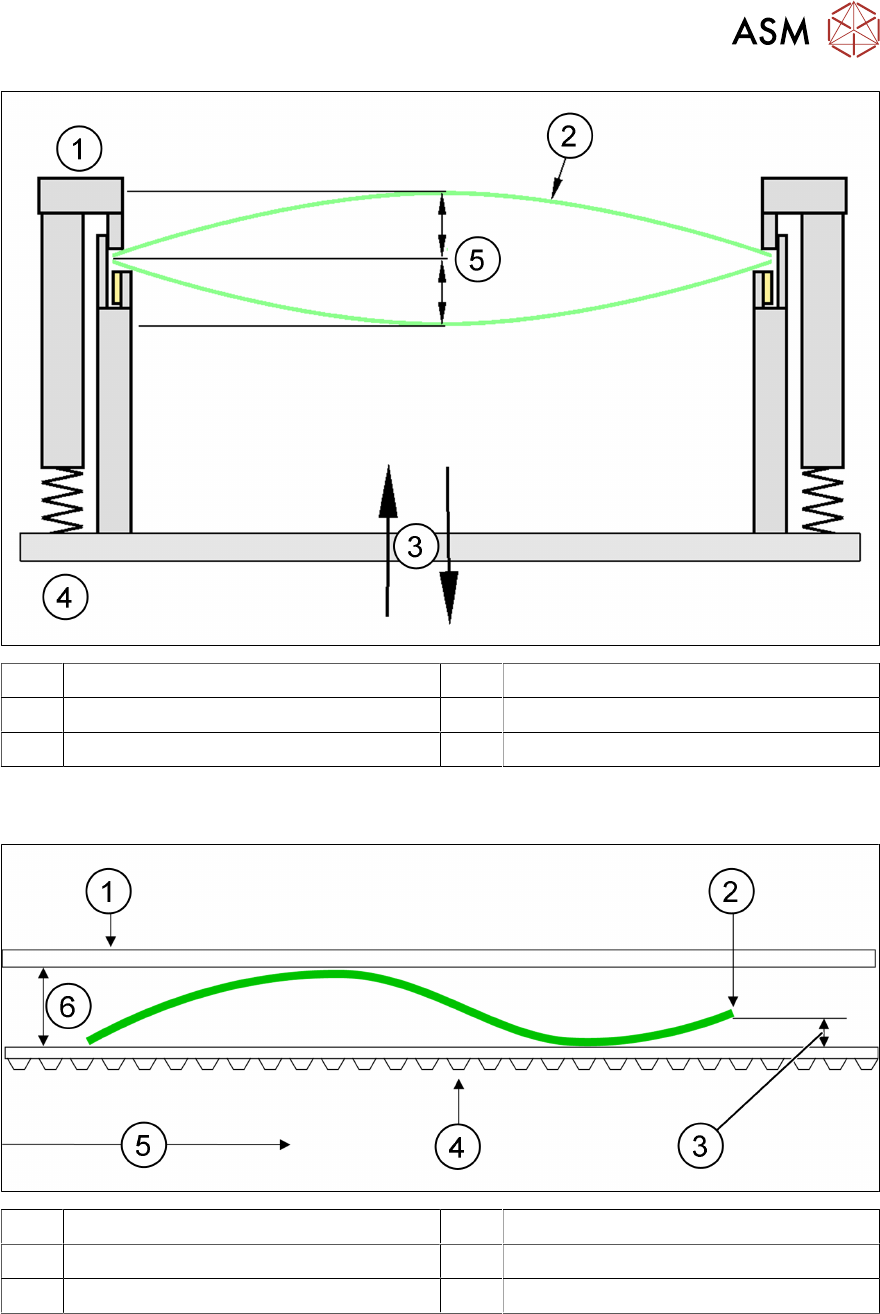
3.1.5 Definition of PCB warpage
This is the maximum allowable PCB warpage for the SPI to be able to measure accurately.
3.1.5.1 PCB warpage on the conveyor
PCB warpage across the direction of travel max. 1% of the PCB diagonal, but not exceeding
±5mm.
3 Machine description
3.1 Overview of the modules
Instruction manual ASM ProcessLens 03/2021 51
1 Fixed clamped edge 2 Printed circuit board
3 Movable clamping device 4 Conveyor rail
5 +/- 4.5 mm
PCB warpage in the direction of transport + PCB thickness < 5.5 mm. Bending up of board edge
max. 2.5 mm.
1 Fixed clamped edge 2 Front board edge
3 Max. 2.5 mm 4 Conveyor belt
5 PCB transport direction 6 5.5 mm
3 Machine description
3.1 Overview of the modules
52 Instruction manual ASM ProcessLens 03/2021
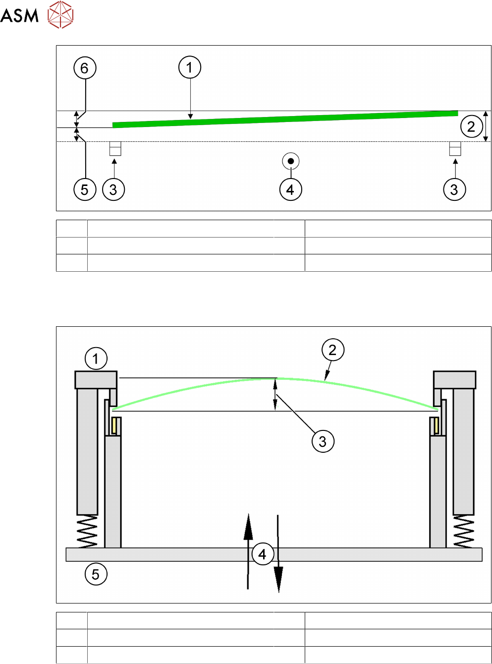
1 Front board edge 2 Max. 2.5 mm
3 Conveyor rail 4 PCB transport direction
5 Max. 2.5 mm 6 Max. 3 mm
3.1.5.2 Maximum PCB warpage allowed during processing of the board
There is active PCB warpage measurement and tracking during the inspection so that images re-
main in sharp focus, ensuring best height measurement accuracy on the market.
1 Fixed clamped edge 2 Printed circuit board
3 ≤ 2 mm 4 Movable clamping device
5 Conveyor rail
PCB warpage down, max. 4.5 mm