00900330-01_UM_ASM-ProcessLens_EN.pdf - 第66页
4 Setting up and commissioning 4.3 Setting up the machine 66 Instruction manual ASM ProcessLens 03/2021 WARNING Risk of injury Please note the following points before you raise the machine in order to avoid irreversible …
4 Setting up and commissioning
4.3 Setting up the machine
Instruction manual ASM ProcessLens 03/2021 65
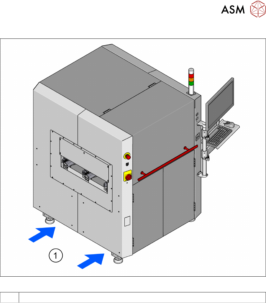
4.3.2 Lifting and transporting the machine with the forklift truck
Fig.43: Contact surfaces - forks parallel to the direction of PCB transport
1 Contact surface for forklift truck forks
► Position the forklift truck at right angles to the PCB conveyor and open the forks until the con-
tact surfaces of the machine lie evenly on the forks.
4 Setting up and commissioning
4.3 Setting up the machine
66 Instruction manual ASM ProcessLens 03/2021
WARNING
Risk of injury
Please note the following points before you raise the machine in order to avoid irreversible
damage to the machine
► The forks must be aligned parallel to the PCB conveyor.
► Make sure to push the forks all the way through. Not pinching cables. There is an area
in the center of the machine's base plate where there is a fan. If the forks are not go-
ing through fully, they could lift up the machine and be in contact with the fan and not
the machine's base plate which means the fan would get destroyed.
► The forks may only be opened to a degree which ensures that they are still within the
contact area of the machine underside (see 4.1 - 3).
► Do not increase the distance between the forks so that the machine is lifted outside
this contact surface. This would lead to deformation of the machine frame and/or dam-
age to the cables and leads.
► Make sure that the forks are evenly loaded when you lift the machine.
► A firm support between the forks and machine will prevent the machine tilting when it
is raised. This will also prevent a one-sided load on the machine feet, which would de-
form the fixing of the machine feet. We recommend that a second person watch the
machine as it is raised, and make sure that the machine does not tip to one side when
lifted with the forklift.
WARNING
Transporting the machine
When you are transporting the machine, make sure that all the feet are clear of the floor. If
they are not clear, the feet will drag along the floor or bump into obstacles. This could dam-
age the machine foot fixing in the machine frame.
► With the forklift, raise the machine approximately 35 cm. This prevents the risk of any
injuries to your feet if the machine feet are unintentionally lowered.
4.3.3 Fitting attached parts
The machine is delivered with the monitor, keyboard and tower lamp dismantled. To fit these com-
ponents, proceed as follows:
●
To fit the tower lamp see section 4.3.3.2 "Fitting the tower lamp" [}66].
●
To fit the monitor see section 4.3.3.3 "Fixing the monitors" [}66].
► Hook up the keyboard fixture and connect the keyboard.
4.3.3.1 Checking and setting the protective cover switch
► Check the function of the protective cover switch (see section 2.5.2.3 "Position of protective
switch on the machine" [}38].
► Adjust the protective cover switch if necessary (see service manual).
4.3.3.2 Fitting the tower lamp
► Remove the cover on the tower lamp base.
► Fix the connector between the machine and the tower lamp.
► Insert the tower lamp into the holder.
► Put on the cover onto the tower lamp.
4.3.3.3 Fixing the monitors
► Install and secure the monitor in the bracket using 4x M4 x 8mm screws with washer.
► Insert the power cable.
► Insert and tighten the screws of the VGA cable.
4 Setting up and commissioning
4.3 Setting up the machine
Instruction manual ASM ProcessLens 03/2021 67
4.3.4 Tools and equipment
You will need the following tools and equipment to adjust the height of your machine:
●
Open-ended wrench SW 19, SW 30, SW 36
●
One or two machine spirit level(s): accuracy 0.02 mm/m
●
Forklift truck (specification see 4.1.4.3).
4.3.5 Adjusting the machine height
The machine can be set at any PCB conveyor height within the following range:
●
900 mm ± 15 mm
●
930 mm ± 15 mm
●
950 mm ± 15 mm
CAUTION
Foot spacers
When using the 950 ± 15 mm PCB conveyor height, foot spacers are required to maintain
ASM ProcessLens measurement accuracy and stability.
NOTICE
PCB conveyor height
The PCB conveyor height is the distance between the top edge of the PCB conveyor belt
and the bottom edge of the machine feet.