Autosite_Users_Manual.pdf - 第105页
Trans lation Fo rmats AutoSite User Manual B-7 Texas Instruments SDSMAC Fo rmat (320), Code 04 Data file s in the S DSMAC (320) for mat consis t of a st art-of-file re cord, data records, and an end-of-file record. See F…

Translation Formats
B-6 AutoSite User Manual
Note: Data without a start or end code may be input to or output from the
programmer by use of alternate data translation format codes. These are
ASCII-BNPF, 05; ASCII-BHLF, 06; ASCII-B10F, 07.
A single data byte can be aborted if the programmer receives an E
character between B and F characters. Data will continue to be stored in
sequential RAM addresses. Data are output in 4-byte lines with a space
between bytes.
Translation Formats
AutoSite User Manual B-7
Texas Instruments SDSMAC Format (320), Code 04
Data files in the SDSMAC (320) format consist of a start-of-file record,
data records, and an end-of-file record. See Figure B-2. The format is used
for Texas Instruments’ 320 line of processors. It is very similar to format
90; the only difference is that the address fields represent 16-bit data
words rather than bytes
Each record is composed of a series of small fields, each initiated by a tag
character. the programmer recognizes and acknowledges the following
tag characters:
0 or K—followed by a file header.
7—followed by a checksum which the programmer acknowledges.
8—followed by a checksum which the programmer ignores.
9—followed by a load address which represents a word location.
B—followed by 4 data characters (16-bit word).
F—denotes the end of a data record.
*—followed by 2 data characters.
The start-of-file record begins with a tag character and a 12-character file
header. The first four characters are the word count of the 16-bit data
words; the remaining file header characters are the name of the file and
may be any ASCII characters (in hex notation). Next come interspersed
address fields and data fields (each with tag characters). The address
fields represent 16-bit words. If any data fields appear before the first
address field in the file, the first of those data fields is assigned to address
0000. Address fields may be expressed for any data word, but none are
required.
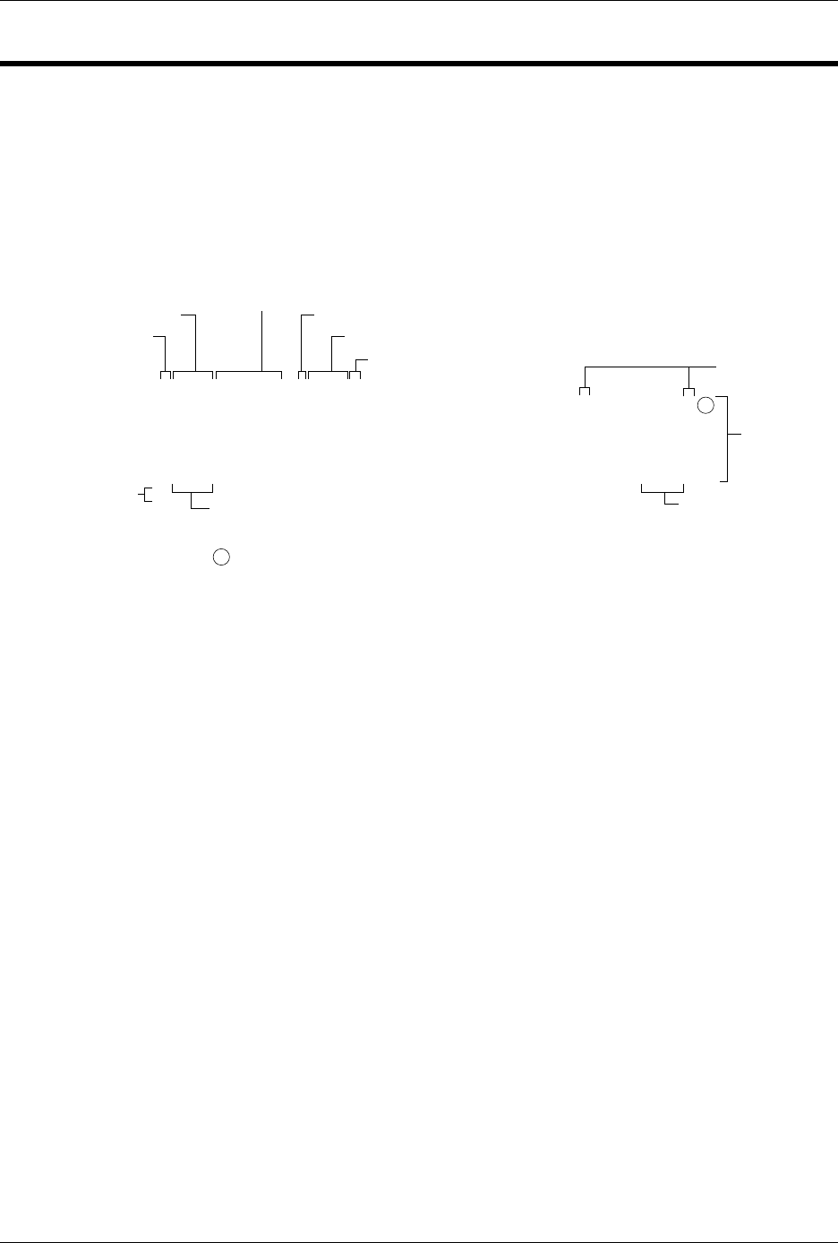
Figure B-2
An Example of TI SDSMAC Format
00028 7FDCFF
90000BFFFFBFFFFBFFFFBFFFFBFFFFBFFFFBFFFFBFFFF7F400F
90008BFFFFBFFFFBFFFFBFFFFBFFFFBFFFFBFFFFBFFFF7F3F8F
90010BFFFFBFFFFBFFFFBFFFFBFFFFBFFFFBFFFFBFFFF7F3FFF
90018BFFFFBFFFFBFFFFBFFFFBFFFFBFFFFBFFFFBFFFF7F3F7F
90020BFFFFBFFFFBFFFFBFFFFBFFFFBFFFFBFFFFBFFFF7F3FEF
:
Tag Character
Word Count
Tag Character
Checksum
Tag Character
Filename
End-of-File Record
Load Address
Tag Characters
Data
Records
Checksum
0429-2
LEGEND
Nonprinting Carriage Return, with optional line feed and nulls
determined by null count.

Translation Formats
B-8 AutoSite User Manual
The record ends with a checksum field initiated by the tag character 7 or
8, a 4-character checksum, and the tag character F. The checksum is the
two's complement of the sum of the 8-bit ASCII values of the characters,
beginning with the first tag character and ending with the checksum tag
character (7 or 8).
Data records follow the same format as the start-of-file record but do not
contain a file header. The end-of-file record consists of a colon (:) only.
The output translator sends a CTRL-S after the colon.
During download or input from disk operations the destination address
for the data is calculated in the following manner:
Memory address =
(load address x 2) – I/O address offset + begin address
During upload or output to disk operations the load address sent with
each data record is calculated in the following manner:
Load address = I/O address offset / 2
The Memory begin address, I/O address offset, and User data size
parameters represent bytes and must be even values for this format. The
upload record size must also be even for this format (default is 16).
Note: If the data will be programmed into a 16-bit device to be used in a
TMS320 processor-based system, the odd/even byte swap switch must be
enabled.